
Wire harness storing device

A storage device and wire harness technology, applied in the directions of transportation and packaging, transportation of filamentous materials, thin material handling, etc., can solve the problems of reduced work efficiency, disorderly placement of wire harnesses, slow taking efficiency, etc., to improve applicability, avoid The effect of space constraints and easy access to wire harnesses

Inactive Publication Date: 2020-09-11
曾缤
View PDF0 Cites 1 Cited by
  • Summary
  • Abstract
  • Description
  • Claims
  • Application Information

AI Technical Summary

Problems solved by technology

[0003] In daily work, wire harnesses are generally simply stored in boxes. There is no classification for wire harnesses of various sizes. The efficiency is slow, thereby reducing the work efficiency. Based on this, we propose a wire harness storage device to solve the above problems

Method used


Image

  • Wire harness storing device
  • Wire harness storing device
  • Wire harness storing device

Examples


Embodiment 1

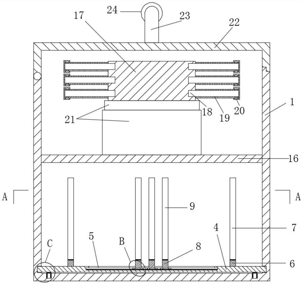
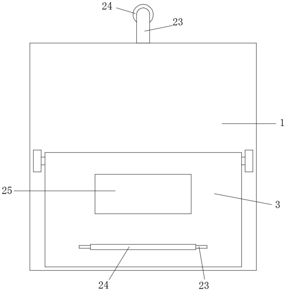
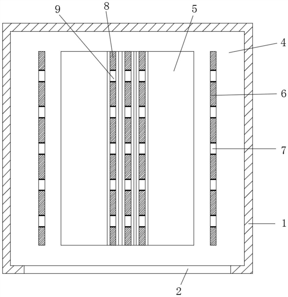
[0024] see Figure 1-6 , a wire harness storage device, including a wire harness storage box 1, the side of the wire harness storage box 1 is provided with a pick-and-place hole 2, and the outer side of the pick-and-place hole 2 is provided with a protective door 3, and the protective door 3 is equipped with The damped rotation is installed on the side of the wire harness storage box 1, the bottom of the wire harness storage box 1 is detachably installed with a wire harness placement assembly, and the wire harness placement assembly includes a mounting plate detachably installed on the wire harness storage box 1 4. The mounting plate 4 is provided with a T-shaped chute 5, and the mounting plate 4 located on both sides of the T-shaped chute 5 is fixedly installed with a fixed placement plate 6, and the fixed placement plate 6 is provided with a number of uniform Placement slots 7 are arranged, and a plurality of T-shaped movable placement plates 8 are installed slidingly with d...

Embodiment 2

[0032] This embodiment is further improved on the basis of the embodiment. The improvement is that: a label slot 25 is fixedly installed on the protective door 3; The corresponding diameter labels make it easy for people to clearly distinguish the wire harnesses in each wire harness storage box 1, and further improve the storage of the wire harnesses.

[0033] The working principle of this embodiment is: by setting the label groove 25, a diameter label corresponding to the diameter of the wire harness in the wire harness storage box 1 is placed in the label groove 25, so that people can clearly distinguish the wire harness in each wire harness storage box 1, More perfect storage of wiring harness.


PUM


Abstract

The invention discloses a wiring harness storing device. The wiring harness storing device comprises a wiring harness storing box body, wherein a wiring harness placing assembly is detachably mountedat the bottom of the wiring harness storing box body; the wiring harness placing assembly comprises a mounting plate; a T-shaped sliding groove is formed in the mounting plate; a fixed placing plate is fixedly mounted on the mounting plate; a plurality of uniformly distributed placing grooves are formed in the fixed placing plate; a plurality of T-shaped movable placing plates are slidably mountedin the T-shaped sliding groove; and the T-shaped movable placing plate is provided with movable placing grooves corresponding to the placing grooves one by one. According to the wire harness storingdevice, through setting the mounting plate, the fixed placing plate and the T-shaped movable placing plates, the positions of the T-shaped movable placing plates are adjusted according to the lengthsof wire harnesses, the wire harnesses with different lengths are clamped in the mutually corresponding placing grooves and the movable placing grooves, the storing and limiting of the wire harnesses with the same diameter and different lengths are achieved, and the wire harnesses with different sizes are prevented from being randomly placed together, so that the situation that the wire harnesses with different sizes are not convenient to take during using while the wire harnesses are not attractive is avoided.

Description

technical field [0001] The invention relates to the field of wire harness collection equipment, in particular to a wire harness storage device. Background technique [0002] The wiring harness is a group of metal wires and cables bound together to carry the signal and power connection between the equipment. It is the wiring part that connects various electrical equipment in the automotive circuit. composition. [0003] In daily work, wire harnesses are generally simply stored in boxes. There is no classification for wire harnesses of various sizes. The efficiency is slow, thereby reducing the work efficiency. Based on this, we propose a wire harness storage device for solving the above problems. Contents of the invention [0004] The object of the invention is to provide a wire harness storage device to solve the problems raised in the background art above. [0005] To achieve the above object, the invention provides the following technical solutions: [0006] A wire h...

Claims


Application Information

Patent Timeline
Patent Type & Authority Applications(China)
IPC IPC(8): B65H49/38
CPCB65H49/38
Inventor 曾缤
Owner 曾缤
Learn More