T-shaped bone plate
A technology of bone plate and plate body, applied in the direction of outer plate, internal bone synthesis, medical science, etc., can solve the problems of adverse reactions of surrounding tissues, easy to wear metal chips, fretting corrosion, etc., to improve the healing rate and prevent fretting. Corrosion and oppression reduction effects
- Summary
- Abstract
- Description
- Claims
- Application Information
AI Technical Summary
Problems solved by technology
Method used
Image
Examples
Embodiment 1
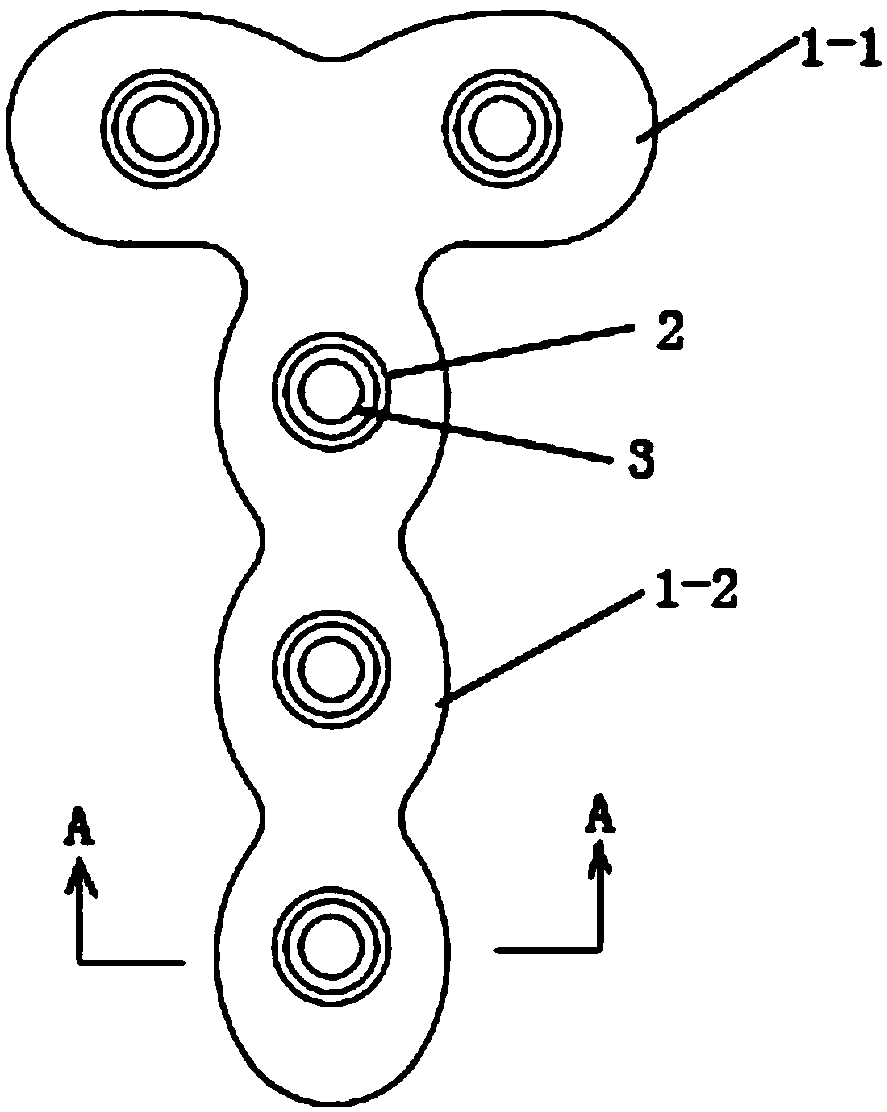
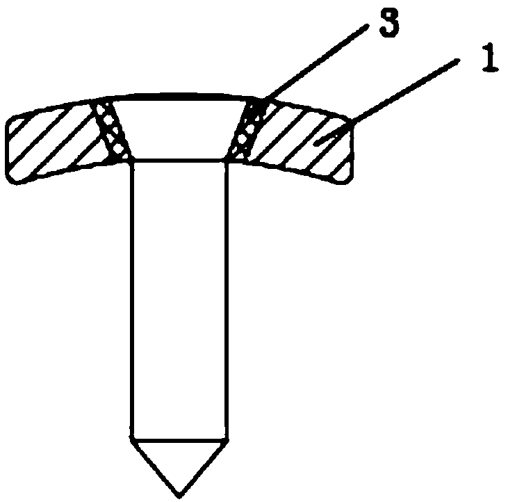
[0033] Such as Figure 1-3 Shown is the T-shaped bone plate of this embodiment, which includes a T-shaped flat plate body 1, and the plate body 1 is divided into a head 1-1 and a body 1-2 integrally formed. The side of the board body 1 is concave-convex and wavy, and the board body 1 is provided with screw holes 2, the screw holes 2 are evenly distributed on the board body 1, and the side of the board body 1 is located between two adjacent screw holes 2 A concave point is formed, and a convex point is formed at the position where the screw hole 2 is located. The screw hole 2 is in the shape of a circular cone, and the inner wall of the screw hole 2 has an internal thread.
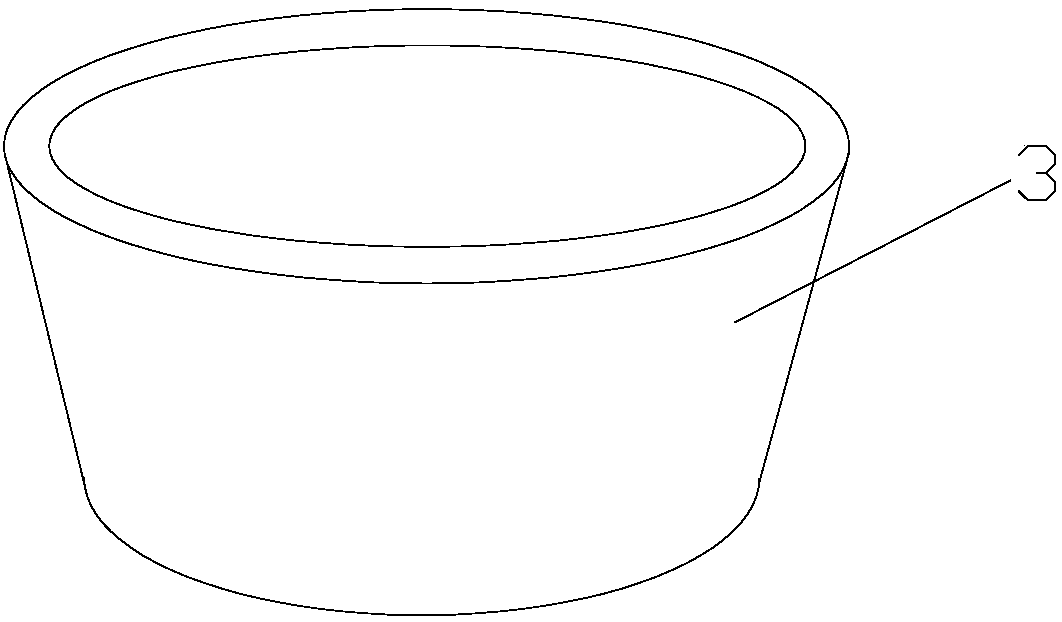
[0034] An annular gasket 3 is placed in the screw hole 2 , the inner and outer walls of the gasket 3 are smooth, and the gasket 3 is in contact with the screw hole 2 . The liner 3 is made of polyethylene, or polyetheretherketone or polylactic acid that can be absorbed and degraded by the human body.
Embodiment 2
[0036] Such as Figure 4-7 Shown is the T-shaped bone plate of this embodiment, which includes a T-shaped flat plate body 1, and the plate body 1 is divided into a head 1-1 and a body 1-2 integrally formed. The plate body 1 is provided with a screw hole 2, the screw hole 2 is in the shape of a circular platform, the inner wall of the screw hole 2 has an internal thread, the screw hole 2 is distributed at the end of the head 1-1 and the body 1-2, the head 1-1 A light hole 4 with a smooth inner wall is opened at the connection position with the body part 1-2, and the light hole 4 can reduce the pressure generated by the bone plate on the human bone. The side surface of the plate body 1 is concave-convex and wavy. The side of the plate body 1 is located between two adjacent screw holes 2 to form a concave point, and the position where the screw holes 2 are located forms a convex point. Through the concave-convex wavy design, It can reduce the pressure on human bones.
[0037] A...
Embodiment 3
[0041] Such as Figure 8 Shown is the T-shaped bone plate of this embodiment, which includes a T-shaped flat plate body 1, and the plate body 1 is divided into a head 1-1 and a body 1-2 integrally formed. The side surface of the plate body 1 is concave-convex and wavy, and the plate body 1 is provided with a screw hole 2. The end of the body portion 1-2 connected to the head 1-1 is the head end, and the end of the body portion 12 is far away from the head 1-1. One end is the end, and the screw holes 2 are distributed on the ends of the head 1-1 and the body 1-2. On the side of the plate body 1, a concave point is formed at the position between two adjacent screw holes 2, where the screw holes 2 are located. The parts form bumps. The screw hole 2 is in the shape of a circular cone, and the inner wall of the screw hole 2 has an internal thread.
[0042] An annular gasket 3 is placed in the screw hole 2 , the inner and outer walls of the gasket 3 are smooth, and the gasket 3 is...
PUM
 Abstract
Description
Claims
Application Information
 - Generate Ideas
- Intellectual Property
- Life Sciences
- Materials
- Tech Scout
- Unparalleled Data Quality
- Higher Quality Content
- 60% Fewer Hallucinations
Browse by: Latest US Patents, China's latest patents, Technical Efficacy Thesaurus, Application Domain, Technology Topic, Popular Technical Reports.
© 2025 PatSnap. All rights reserved.Legal|Privacy policy|Modern Slavery Act Transparency Statement|Sitemap|About US| Contact US: help@patsnap.com


