Intramedullary nail locking mechanism
A technology of intramedullary nails and locking nails, which is applied in the field of intramedullary nail locking mechanisms, can solve problems such as adverse reactions and fretting corrosion of the surrounding tissues of the human body, and achieve the effects of preventing fretting corrosion, increasing reliability, and preventing adverse effects
- Summary
- Abstract
- Description
- Claims
- Application Information
AI Technical Summary
Problems solved by technology
Method used
Image
Examples
Embodiment 1
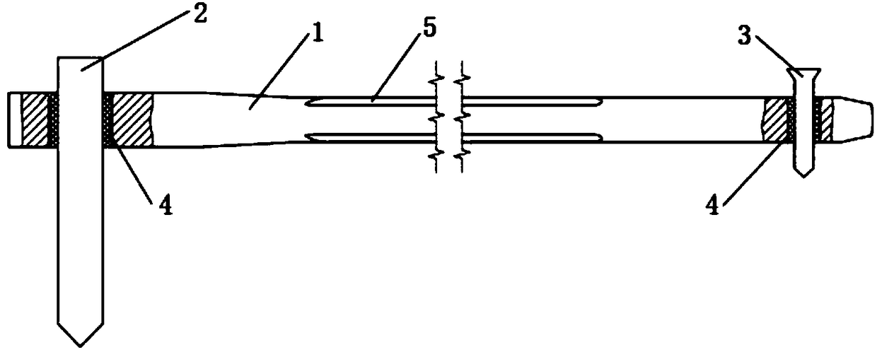
[0028] Such as Figure 1-2 As shown, it is the intramedullary nail locking mechanism of this embodiment, which includes a main nail 1, a lag screw 2 and a locking nail 3, the main nail 1 is a long shaft with a cavity inside, and the lag screw 2 is arranged on the main nail 1 near the tension hole, the tension hole is a non-circular hole, and the locking nail 3 is set in the locking hole at the distal end of the main nail 1. The outer wall of the main nail 1 has a decompression surface 5 extending along the elongation direction of the main nail 1 .
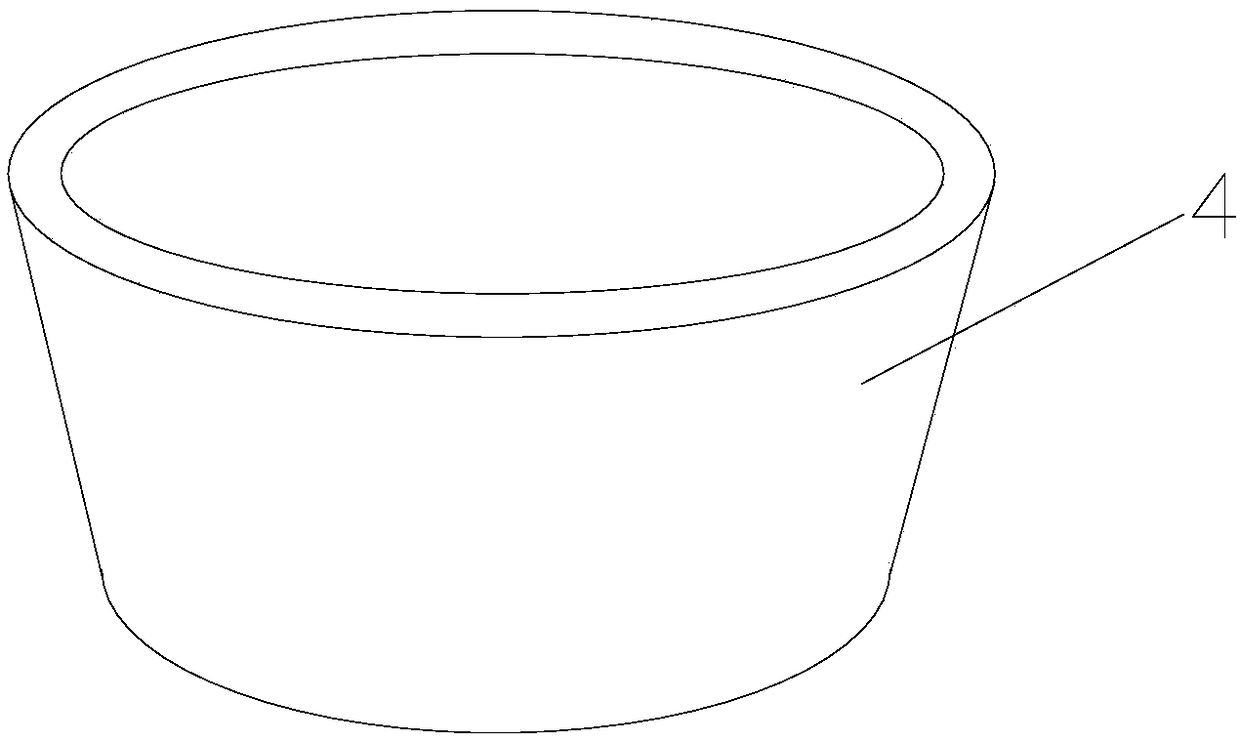
[0029] An annular liner 4 is placed in the tension hole and the keyhole, the inner wall and the outer wall of the liner 4 are smooth, and the liner 4 resists the tension hole or the keyhole. The liner 4 is made of polyethylene, or polyetheretherketone or polylactic acid that can be absorbed and degraded by the human body.
Embodiment 2
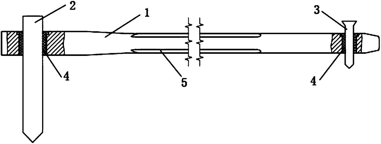
[0031] Such as Figure 3-4 As shown, it is the intramedullary nail locking mechanism of this embodiment, which includes a main nail 1, a lag screw 2 and a locking nail 3, the main nail 1 is a long shaft with a cavity inside, and the lag screw 2 is arranged on the main nail 1 near the tension hole, the tension hole is a non-circular hole, and the locking nail 3 is set in the locking hole at the distal end of the main nail 1. The outer wall of the main nail 1 has a decompression surface 5 extending along the elongation direction of the main nail 1 .
[0032] An annular liner 4 is placed in the tension hole and the keyhole, and one end of the liner 4 has a protruding step 41. The tension hole and the keyhole are divided into a head end and an end according to their pointing directions, and the tension hole and the keyhole There is a notch adapted to the step 41 at the head end of the pad. When the pad 4 is arranged in the tension hole or the lock hole, the step 41 is stuck in th...
Embodiment 3
[0035] Such as Figure 5-7 As shown, it is the intramedullary nail locking mechanism of this embodiment, which includes a main nail 1, a lag screw 2 and a locking nail 3, the main nail 1 is a long shaft with a cavity inside, and the lag screw 2 is arranged on the main nail 1 near the tension hole, the tension hole is a non-circular hole, and the locking nail 3 is set in the locking hole at the distal end of the main nail 1. The outer wall of the main nail 1 has a decompression surface 5 extending along the elongation direction of the main nail 1 .
[0036] An annular liner 4 is placed in the tension hole and the keyhole, the inner wall and the outer wall of the liner 4 are smooth, and the liner 4 resists the tension hole or the keyhole. The liner 4 is made of polyethylene, or polyetheretherketone or polylactic acid that can be absorbed and degraded by the human body.
[0037] The main nail 1 is formed by plugging two nails. One end of the insertion part on the main nail 1 h...
PUM
 Abstract
Description
Claims
Application Information
 - R&D
- Intellectual Property
- Life Sciences
- Materials
- Tech Scout
- Unparalleled Data Quality
- Higher Quality Content
- 60% Fewer Hallucinations
Browse by: Latest US Patents, China's latest patents, Technical Efficacy Thesaurus, Application Domain, Technology Topic, Popular Technical Reports.
© 2025 PatSnap. All rights reserved.Legal|Privacy policy|Modern Slavery Act Transparency Statement|Sitemap|About US| Contact US: help@patsnap.com


