
Alarm generation method and system

A technology for generating system and intelligent alarms, applied in transmission systems, digital transmission systems, data exchange networks, etc., it can solve the problem of difficulty in alarm prevention and predictive analysis, failure to realize intelligent and dynamic alarms, and alarm systems that cannot be separated from alarms. mode and other issues, to achieve the effect of realizing the intelligence and automation of alarms, saving manual configuration and troubleshooting, and improving the accuracy of alarms

Active Publication Date: 2018-06-26
SHANXI CHINA MOBILE COMM CORP +1
View PDF6 Cites 21 Cited by
  • Summary
  • Abstract
  • Description
  • Claims
  • Application Information

AI Technical Summary

Problems solved by technology

In order to distinguish the severity of alarms, several levels of values ​​(general, important, serious, urgent, etc.) are also set for indicators. This alarm technology will generate many levels of alarms, and it is easy to generate false alarms (such as: indicator An instantaneous value is greater than the set threshold, but then the index returns to normal), some relatively complete monitoring systems such as mobile BOMC system, telecom ITSM system, are composed of CMDB, service process, basic platform monitoring, business monitoring and other supporting systems , but the design of its alarm system is still inseparable from the indicator-based threshold alarm mode, and has not yet realized intelligent and dynamic alarms. It still uses post-processing methods to deal with large-scale alarms and false alarms.
Solve problems through functions such as automatic alarm elimination, automatic alarm escalation, automatic alarm processing process, and personalized alarm SMS subscription reminders, which are difficult to achieve alarm prevention and predictive analysis

Method used


Image

  • Alarm generation method and system
  • Alarm generation method and system
  • Alarm generation method and system

Examples


Embodiment Construction

[0018] Features and exemplary embodiments of various aspects of the present invention will be described in detail below with reference to the accompanying drawings. In the following detailed description, numerous specific details are set forth in order to provide a thorough understanding of the present invention. It will be apparent, however, to one skilled in the art that the present invention may be practiced without some of these specific details. The following description of the embodiments is only to provide a better understanding of the present invention by showing examples of the present invention. The present invention is by no means limited to any specific configurations and algorithms presented below, but covers any modification, substitution and improvement of elements, components and algorithms without departing from the spirit of the invention. In the drawings and the following description, well-known structures and techniques have not been shown in order to avoi...


PUM


Abstract

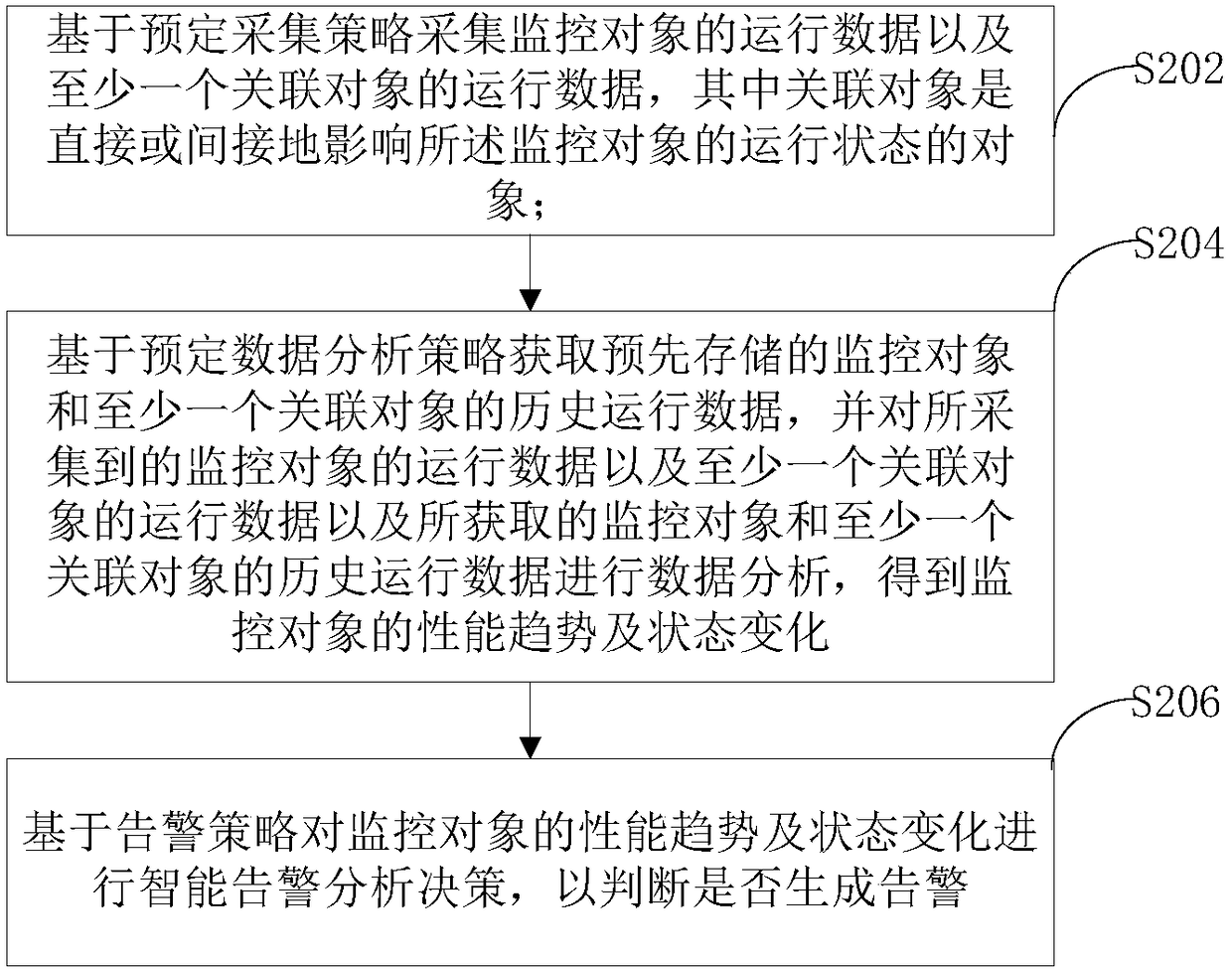
The invention provides an alarm generation method and system. The alarm generation method is carried out in a cloud computing environment on the basis of a big data analysis technology. The method includes the following steps that: the operation data of a monitoring object and the operation data of at least one association object are collected on the basis of a predetermined collection policy, wherein the association objects are objects directly or indirectly affecting the operation state of the monitoring object; the pre-stored historical operation data of the monitoring object and the at least one association object are acquired on the basis of a predetermined data analysis policy, and data analysis is performed on the collected operation data of the monitoring object, the operation dataof the at least one association object and the acquired historical operation data of the monitoring object and the at least one association object, so that the performance trend and state change of the monitored object is obtained; and intelligent alarm analysis decision is performed on the performance trend and state change of the monitored object on the basis of an alarm policy, whether an alarm is to be generated is determined.

Description

technical field [0001] The present invention generally relates to the field of monitoring alarms in the field of cloud computing, and more particularly relates to an alarm generation method and system. Background technique [0002] With the implementation of cloud computing, big data and distributed related technologies, the number of equipment and services of telecom operators has increased suddenly, and the types and numbers of alarms have also increased. Therefore, the workload of resource monitoring and operation and maintenance will also increase. How to locate fault alarms more accurately, eliminate false alarms, reduce repetitive alarms, and realize correlated alarms has become an urgent problem to be solved. [0003] Most monitoring systems now generally use threshold alarms, which are realized mainly by setting a threshold value for the indicators that need to be monitored. When the collected indicator data is greater than the set value, an alarm will be generated. ...

Claims


Application Information

Patent Timeline
Patent Type & Authority Applications(China)
IPC IPC(8): H04L12/24
CPCH04L41/0604H04L41/0631
Inventor 卢山李斌
Owner SHANXI CHINA MOBILE COMM CORP
Learn More