Stone grinding and polishing machine

A mechanical and stone technology, applied in the field of stone grinding and polishing machinery, can solve the problems of unsustainable water supply, inability to remove small stone particles, and affect the effect of grinding, so as to achieve the effect of increasing service life, increasing quality, and improving grinding effect

Inactive Publication Date: 2018-06-22
WENZHOU POLYTECHNIC
View PDF7 Cites 5 Cited by
  • Summary
  • Abstract
  • Description
  • Claims
  • Application Information

AI Technical Summary

Problems solved by technology

[0003] The current stone grinding machine can only simply polish and polish the stone, and the grinding is relatively simple after the festival, which affects the quality of the grinding. The small stone particles on the road cannot be removed during the grinding process, and it is easy to be damaged during the grinding process. The road surface is damaged, which affects the effect of grinding, and the grinding process is often poor due to dryness, which makes it impossible to continuously replenish the water source and continuously splash water on the road surface, and it is easy to cause waste of water resources, and the current Every time the grinding machine does not have a better energy-saving method, it is easy to cause energy waste

Method used


Image

  • Stone grinding and polishing machine
  • Stone grinding and polishing machine
  • Stone grinding and polishing machine

Examples


Embodiment 1

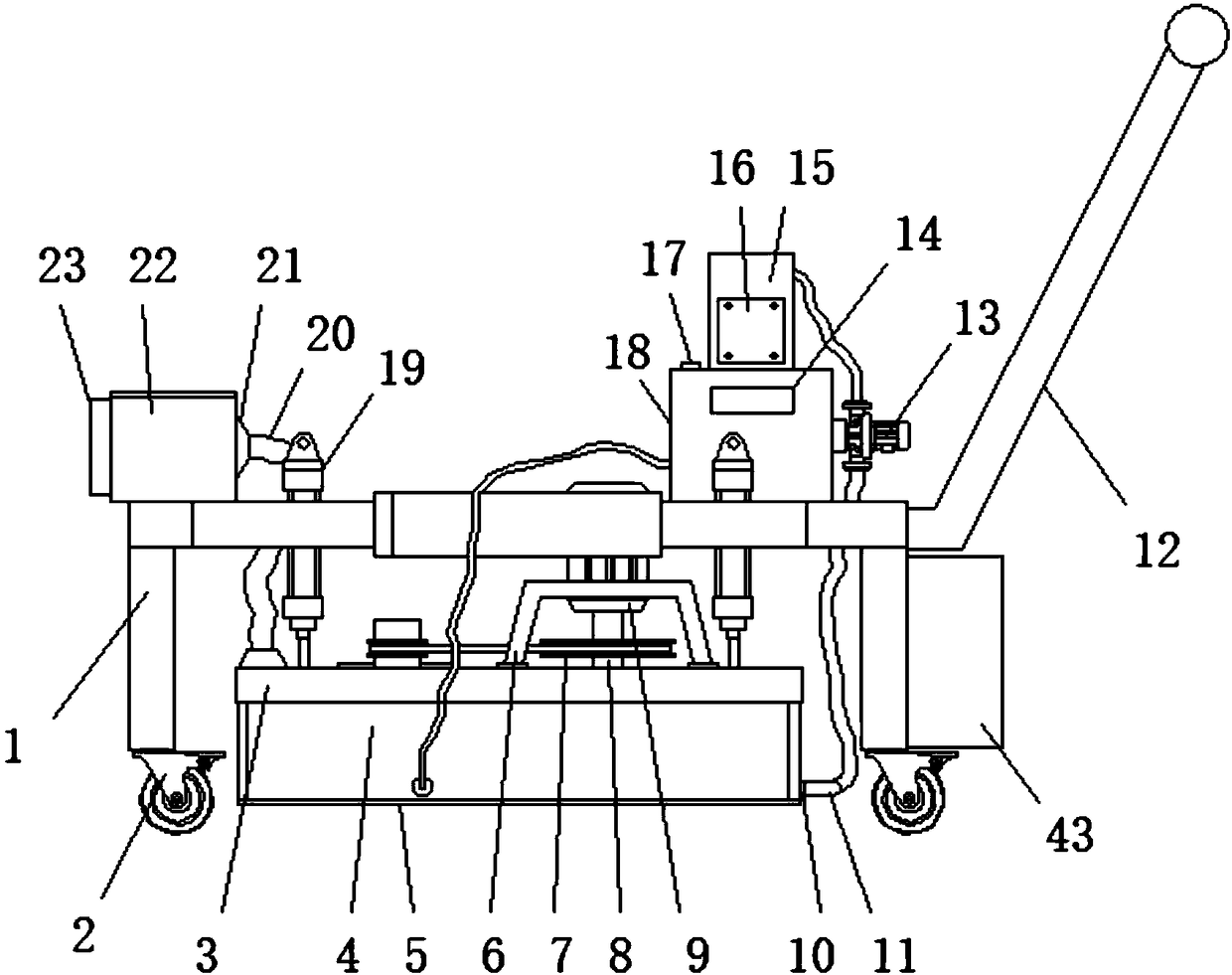
[0024] Example 1, such as Figure 4 When the surface of the stone needs to be cleaned, the negative pressure fan 23 can be turned on to generate a negative pressure airflow, and the fine particles can be sucked into the dust suction pipe 20 through the dust suction cover 30, and discharged into the dust suction bin 22 through the dust discharge cover 21. Inside, the stones are stuck on the surface of the dust removal net 31, and when the inside of the dust collection bin 22 needs to be cleaned, the cleaning cover 40 can be opened to clean the inside.

Embodiment 2

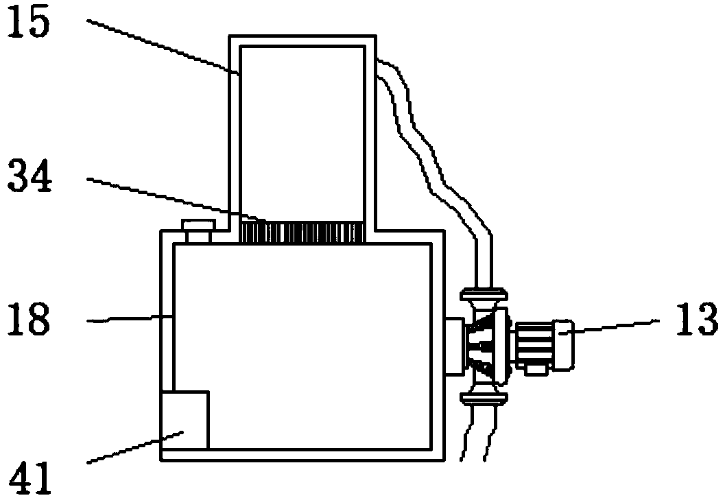
[0025] Example 2, such as Figure 5When water needs to be sprayed during the grinding process, the second water pump 41 can be turned on to spray the water inside the water tank 18 from the water outlet 42 onto the surface of the stone, and the shielding groove 4 can limit the sprayed water to avoid splashing , can save water, can open water pump 13 simultaneously and excess water is sucked into the inside of filter box 15, is discharged into the inside of water tank 18 by the filtration of filter screen 34 again and reclaims water resource, continues to wash stone material.

[0026] Working principle: charge the storage battery 43 before use. When in use, the storage battery 43 supplies power to the device. First, push the device to the top of the stone, adjust the position of the grinding structure through the pneumatic cylinder 19, turn on the motor 9, and drive the first rotating column 8 to rotate. Thereby drive main grinding sheet 29 to rotate, and first belt pulley 7 tr...


PUM


Abstract

The invention discloses a stone grinding and polishing machine which comprises a U-shaped frame. A push rod is mounted at the top of one end of the U-shaped frame, and a storage battery is mounted atthe bottom end of the end, close to the push rod, of the U-shaped frame. A water tank is mounted at the end, close to the push rod, of the upper portion of the U-shaped frame, and a water filling opening is formed in the end, away from the push rod, of the top of the water tank. A second water pump is mounted at the end, away from the push rod, of the bottom end in the water tank. According to thestone grinding and polishing machine, grinding is carried out in the manner of combining a grinding disc and grinding sheets, firstly overall grinding is carried out through the grinding sheets, thenlocal finishing is carried out through the grinding sheets, and therefore the grinding efficiency and quality are improved; the grinding disc and the three groups of grinding sheets are driven through one set of motor, meanwhile, two sets of belt wheels of different radiuses are adopted for transferring power to the grinding disc, and the device transfers power to the auxiliary grinding sheet through two sets of gears of different radiuses; and energy can be effectively saved, and meanwhile the rotating speed of the grinding disc and the auxiliary grinding

Description

technical field [0001] The invention relates to the technical field of abrasive tools, in particular to a stone grinding and polishing machine. Background technique [0002] Stone grinding machine is a kind of stone refurbishment machine. It is mainly used for stone refurbishment and stone refurbishment. The time is too long; and stone renovation is to use chemical and physical methods in a short period of time to restore the original brightness and color of the stone through the grinding and polishing of the stone grinder on the original basis. The brightness of the stone can reach 100% of the effect when it was just laid, which is a relatively common method for people to renovate stone materials. [0003] The current stone grinding machine can only simply polish and polish the stone, and the grinding is relatively simple after the festival, which affects the quality of the grinding. The small stone particles on the road cannot be removed during the grinding process, and i...

Claims


Application Information

Patent Timeline
Patent Type & Authority Applications(China)
IPC IPC(8): B24B7/22B24B27/00B24B47/12B24B55/00B08B5/04B08B3/02
CPCB24B7/22B08B3/02B08B5/04B24B27/0007B24B27/0076B24B47/12B24B55/00
Inventor 赵战锋
Owner WENZHOU POLYTECHNIC
Why Eureka
Try Eureka