Eureka AIR delivers breakthrough ideas for toughest innovation challenges, trusted by R&D personnel around the world.

Full-automatic wire winding and tin soldering machine

A fully automatic, soldering machine technology, applied in welding equipment, auxiliary devices, metal processing, etc., can solve problems such as unsolvable production efficiency and low production capacity

Active Publication Date: 2018-06-22
湖北省磁特科技有限公司
View PDF9 Cites 6 Cited by
  • Summary
  • Abstract
  • Description
  • Claims
  • Application Information

AI Technical Summary

Problems solved by technology

[0003] The technical problem to be solved by the present invention is to provide a fully automatic wire winding soldering machine, which realizes the automatic completion of feeding, feeding, distributing, receiving, winding positioning, loosening and loosening adjustment of the wire, winding, and rest of the workpiece. A series of operations such as wire clipping, tin sticking, post-soldering cooling, sticking flux, soldering, tin scraping, and finished product blanking and recycling. The entire processing process is fully automated without manual participation, and the winding processing and soldering processing The combination of two different processes has high production efficiency and production capacity, which solves the problem that both traditional manual winding and current semi-automatic winding machines cannot realize simultaneous winding and soldering of workpieces, resulting in the inability to solve the problem of low production efficiency and The problem of low productivity

Method used


Image

  • Full-automatic wire winding and tin soldering machine
  • Full-automatic wire winding and tin soldering machine
  • Full-automatic wire winding and tin soldering machine

Examples


Embodiment Construction

[0023] In order to facilitate the understanding of the present invention, the present invention will be described more fully below with reference to the associated drawings. Preferred embodiments of the invention are shown in the accompanying drawings. However, the present invention can be embodied in many different forms and is not limited to the embodiments described herein. On the contrary, the purpose of providing these embodiments is to make the disclosure of the present invention more thorough and comprehensive.

[0024] Unless otherwise defined, all technical and scientific terms used herein have the same meaning as commonly understood by one of ordinary skill in the technical field of the invention.

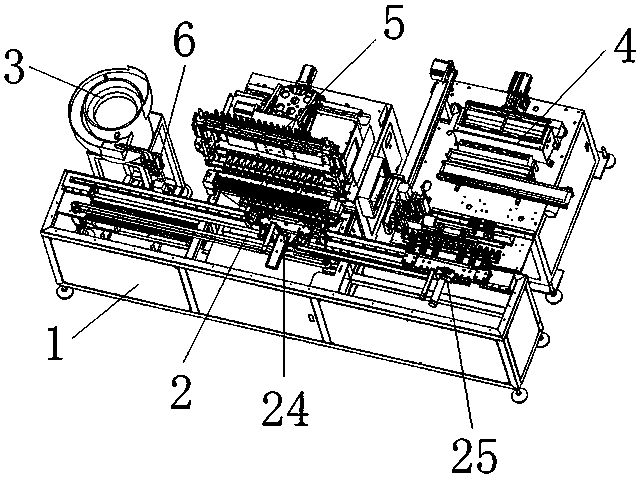
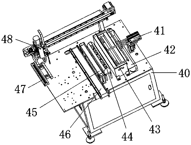
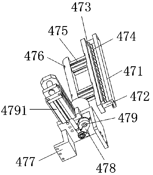
[0025] In this example, refer to Figure 1 to Figure 6 As shown, a fully automatic winding soldering machine of the present invention includes a chassis 1, a fully automatic feeding trolley transmission mechanism 2 is arranged on the top surface of the chassis 1, and a ...


PUM


Abstract

The invention provides a full-automatic wire winding and tin soldering machine which comprises a machine case, a full-automatic feeding trolley transmission mechanism, a full-automatic feeding vibration disc, a full-automatic tin soldering machine, a main full-automatic wire winding machine, and a full-automatic wire winding and discharging mechanism. By adoption of the full-automatic wire windingand tin soldering machine provided by the invention, a workpiece can be subjected to a series of operations such as automatic feeding transmission, automatic material distribution, automatic materialreceiving, automatic wire winding positioning, automatic wire pay-off tightness adjustment, automatic wire winding, automatic waste wire breaking, automatic tin adhering, cooling after tin soldering,automatic flux adhering, automatic tin soldering, automatic tin scraping, and finished product discharging and recycling; the whole machining process can be fully automatically operated and no manualintervention is needed; the two different working procedures of wire-winding machining and tin-soldering machining can be combined together, and then the workpiece can be subjected to wire winding and tin soldering synchronously, thereby greatly improving the production efficiency and the productivity; and besides, the full-automatic wire winding and tin soldering machine is high in wire windingprecision and good in wire winding effect, is more convenient and rapid to use, and meets the large-scale batch production demand of an enterprise.

Description

technical field [0001] The invention relates to a fully automatic winding soldering machine. Background technique [0002] The traditional winding of the bobbin is generally done manually. Manual winding is not only slow, but also leads to high labor intensity and high labor costs for workers. Later, some semi-automatic winding machines appeared on the market, which can realize automatic winding, but they cannot simultaneously solder the coil bobbin, so the winding and soldering operations need to be divided into two different processes and separate different equipment However, it not only cannot solve the problems of low production efficiency and low production capacity, but also leads to high purchase costs for enterprises, which does not meet the requirements of large-scale mass production of enterprises. Contents of the invention [0003] The technical problem to be solved by the present invention is to provide a fully automatic wire winding soldering machine, which r...

Claims


Application Information

Patent Timeline
IPC IPC(8): B23K3/00B23K3/08
CPCB23K3/00B23K3/08
Inventor 陈道武祝兆兵贺赞陈佳明
Owner 湖北省磁特科技有限公司
Why Eureka
Eureka Blog
Learn More