
Nerve stimulator and manufacturing method thereof

A manufacturing method and nerve stimulation technology, which is applied in the field of medical equipment, can solve the problems of small stimulation electrode density and poor stimulation effect, achieve good therapeutic effect, overcome high-density nerve stimulation electrodes, and novel technology

Pending Publication Date: 2018-06-22
HANGZHOU NANOCHAP ELECTRONICS CO LTD
View PDF6 Cites 1 Cited by
  • Summary
  • Abstract
  • Description
  • Claims
  • Application Information

AI Technical Summary

Problems solved by technology

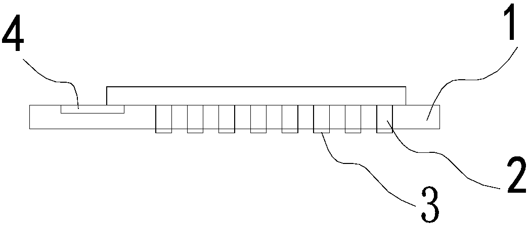
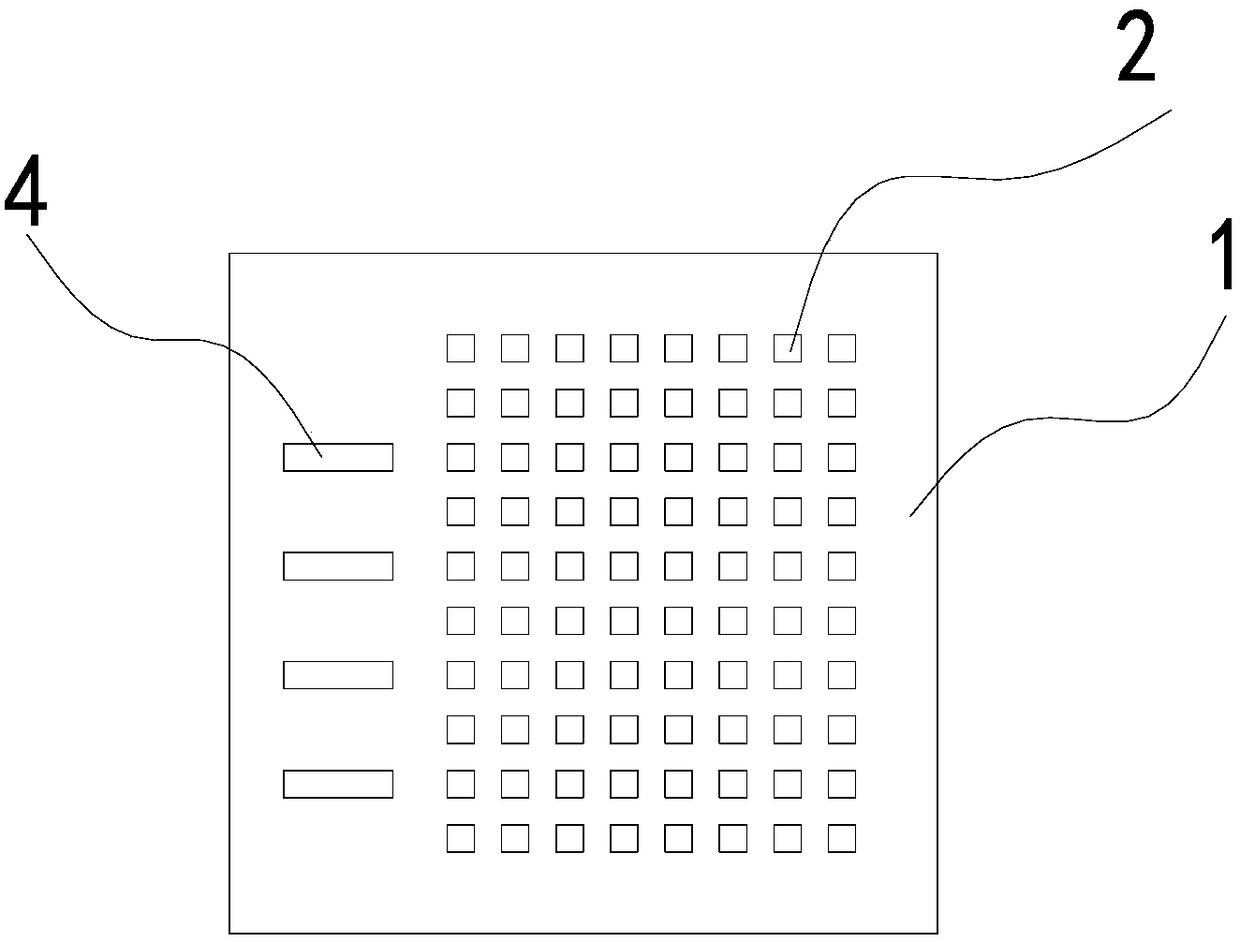
[0005] In order to solve the above-mentioned defects such as too small stimulation electrode density and poor stimulation effect, the present invention provides a brand-new neural stimulator and its manufacturing method. The neural stimulator in the present invention can produce high-density metal stimulators on the substrate. Array, and the chip can be connected on the substrate to avoid the need for a large number of wires to the outside of the eyeball to increase the surgical trauma. The specific scheme is as follows:

Method used


Image

  • Nerve stimulator and manufacturing method thereof
  • Nerve stimulator and manufacturing method thereof
  • Nerve stimulator and manufacturing method thereof

Examples


Embodiment 1

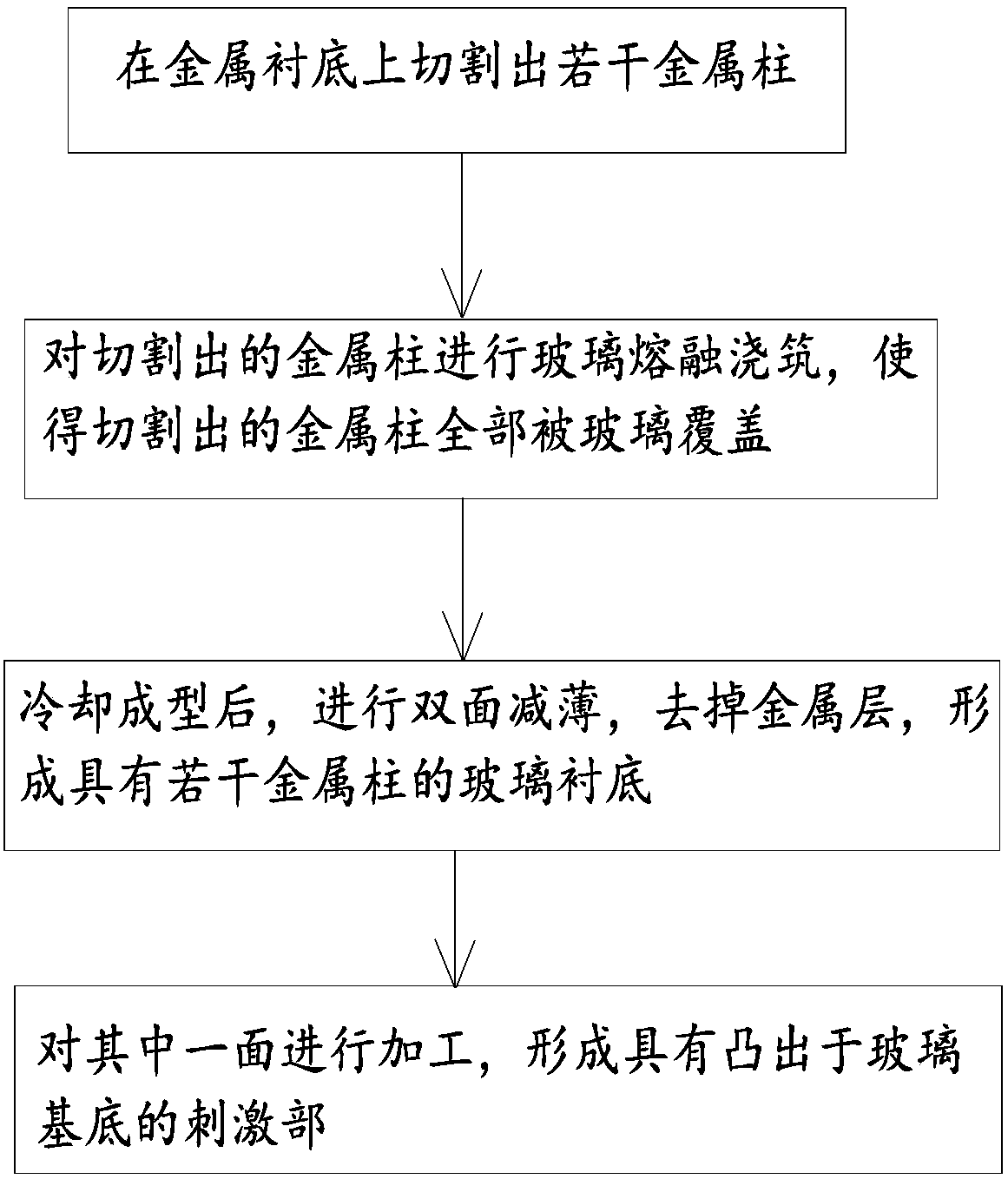
[0057] Step 1: Select a glass substrate and heat it until its material softens;

[0058] Step 2: Squeeze and embed the metal pillars of the metal substrate with several metal pillars cut into the softened glass substrate, so that the metal pillars are completely wrapped by the glass substrate;

[0059] Step 3: cooling and forming.

Embodiment 2

[0061] Step 1: Heating the glass to a molten state in a molten state;

[0062] Step 2: Pouring molten glass on one side of the metal column on the metal substrate, so that the liquid glass covers all the metal column;

[0063] Step 3: cooling and forming.

Embodiment 3

[0065] Step 1: Cut out the metal pillar on the metal substrate and fill it with glass frit;

[0066] Step 2: Heating the metal substrate and the glass powder on it so that the glass powder melts and precipitates on the metal substrate to form a layer of molten glass.

[0067] Step 3: cooling and forming.

[0068] After the above steps, it is generally necessary to further heat and squeeze the glass to reduce the gap between it and the metal column.

[0069] Since the neurostimulator needs to be implanted in the body, the biocompatibility requirements of the materials used are relatively high, so the metal substrate of the metal column and pad structure is generally made of titanium or platinum or iridium or tantalum or gold or other materials. Alloys and other biocompatible metal materials.

[0070] The thickness of the metal substrate is generally between 0.3mm-1.5mm, which can ensure the length of the metal column cut out, and at the same time, the processing efficiency wi...


PUM

PropertyMeasurementUnit
Heightaaaaaaaaaa
Thicknessaaaaaaaaaa
Depthaaaaaaaaaa

Abstract

The invention relates to the field of medical apparatus and instruments, in particular to a nerve stimulator and a manufacturing method thereof. The nerve stimulator comprises a glass base, a plurality of metal columns are disposed on the base, stimulation parts are formed on the surfaces, on the base, of the metal columns, and the density of each metal column is greater than 15 Pin / mm<2>. According to the nerve stimulator, the density of the stimulation parts is high, and the stimulating effect is good. A processing method of the nerve stimulator includes the steps of cutting out a high-density metal column array by using a metal substrate, filling the metal column array with glass and finally conducting double-sided thinning to obtain the nerve stimulator. The manufacturing method has anovel process and unique mode, and the defect that it is difficult to manufacture a high-density nerve stimulation electrode by using other bases such as ceramics in traditional methods is overcome.

Description

technical field [0001] The present invention and the field of medical devices specifically belong to a nerve stimulator and a manufacturing method thereof. Background technique [0002] As an important tool for the treatment of neurological diseases, microelectrode stimulators have attracted more and more attention, and have become an important research direction at present. In the existing retinal microelectrode stimulators, the stimulating electrodes generally adopt flexible MEMS technology. Formed stimulation electrodes, connecting wires, and pads for flip-chip bonding to the ceramic substrate. However, the flexible micro-level wiring is generally wired from the stimulating electrodes to the outside of the eyeball one by one. When the number of stimulating electrodes is too large, the number of wiring will also increase. A large number of wiring will cause the diameter of the outgoing cable to increase, causing postoperative trauma get bigger. [0003] There are also so...

Claims


Application Information

Patent Timeline
IPC IPC(8): A61N1/36A61N1/04
CPCA61N1/0456A61N1/0476A61N1/0492A61N1/36014A61N1/0543A61N1/3605A61N1/0551A61N1/36125B23K26/38C03C27/02H05K1/0306H05K1/11
Inventor 杨佳威杨旭燕
Owner HANGZHOU NANOCHAP ELECTRONICS CO LTD
Learn More