
SMD quartz resonator and processing device and method thereof

A quartz resonator and resonance technology, which is used in metal processing equipment, welding equipment, laser welding equipment, etc., can solve problems such as affecting production efficiency and equipment size, deterioration of weld surface quality, and high production costs. The effect of improving production efficiency, reducing production costs, and reducing material costs

Pending Publication Date: 2018-06-01
SICHUAN MDH TECH CO LTD
View PDF0 Cites 7 Cited by
  • Summary
  • Abstract
  • Description
  • Claims
  • Application Information

AI Technical Summary

Problems solved by technology

[0007] Parallel sealing welding technology is an evolution of spot welding technology. There are the following problems in the application of SMD quartz crystal resonator packaging: 1. The thickness of the metal material to be welded is required to be 0.1-0.25mm, which is difficult to reduce material costs; 2. In order to avoid When the electrode wheel touches the adjacent welding objects, the objects to be welded need to be arranged at a relatively large distance, which affects production efficiency and equipment size. For example, a processing pallet with the size of B4 paper can only carry about 300 pieces, which leads to various The processing machine is huge; 3. The surface of the seam welding electrode is prone to sticking damage, which will deteriorate the quality of the weld surface, and the electrode needs to be repaired regularly, which will affect the maintenance cost; 4. Spot welding must be used for positioning, which will affect the welding efficiency; 5. Spot fixing point Appropriate spacing is required, that is, there are size requirements for the object to be welded, which affects applicability
resulting in high production costs

Method used


Image

  • SMD quartz resonator and processing device and method thereof
  • SMD quartz resonator and processing device and method thereof
  • SMD quartz resonator and processing device and method thereof

Examples


Embodiment Construction

[0047] The principles and features of the present invention are described below in conjunction with the accompanying drawings, and the examples given are only used to explain the present invention, and are not intended to limit the scope of the present invention.

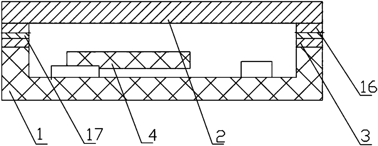
[0048] Such as figure 1 Shown is the structural schematic diagram of the SMD quartz crystal resonator of prior art;

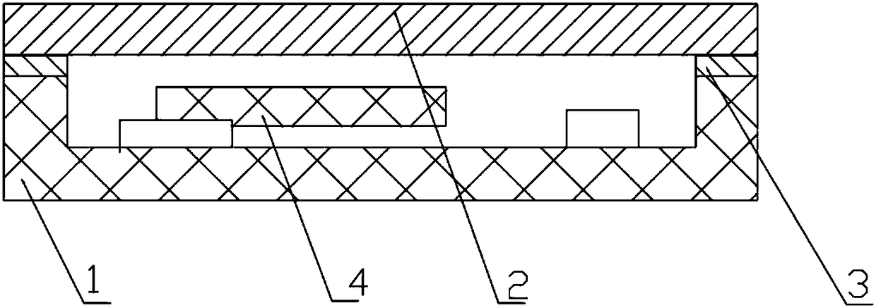
[0049] Such as figure 2 As shown, it is a schematic structural diagram of Embodiment 1 of the present invention: a SMD quartz resonator, including a ceramic base 1, the ceramic base 1 is provided with a cavity for a resonator, and the frame of the ceramic base is provided with The metal plating layer 3 is covered with a metal cover plate 3 .

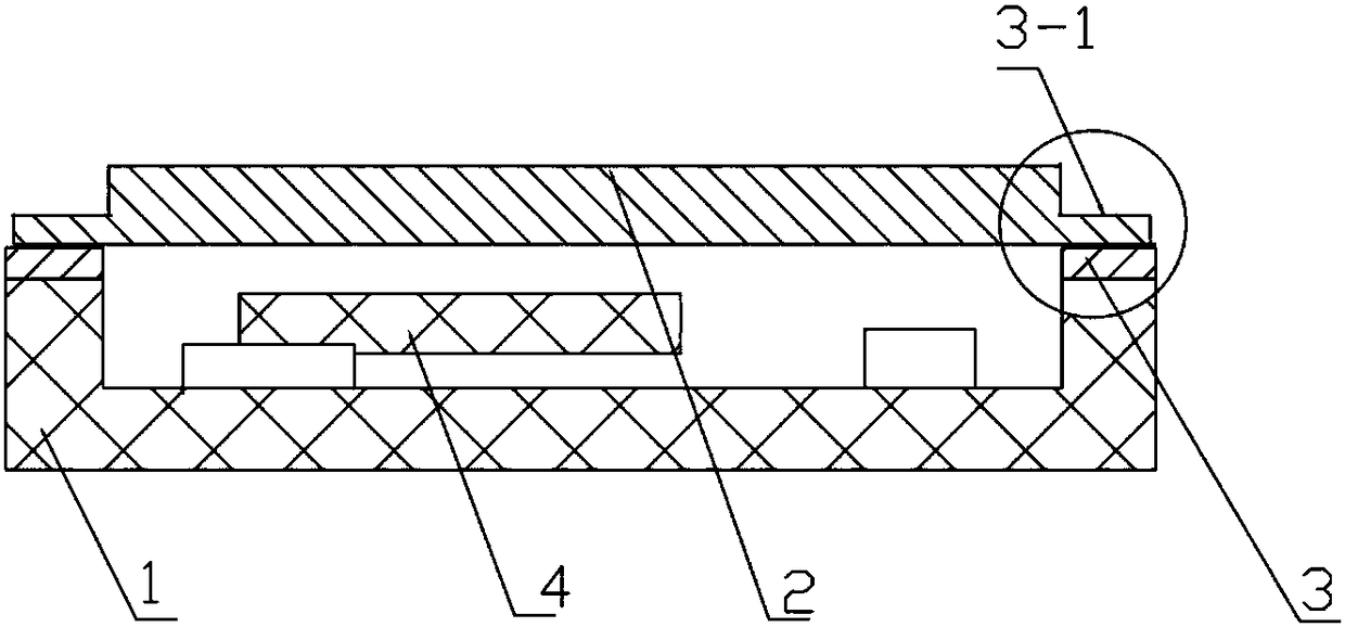
[0050] Such as image 3 As shown, it is a schematic diagram of the structure of Embodiment 2 of the present invention: a SMD quartz resonator, including a ceramic base 1, the ceramic base 1 is provided with a resonator cavity, and the frame of the ceramic b...


PUM

PropertyMeasurementUnit
Thicknessaaaaaaaaaa

Abstract

The invention discloses an SMD quartz resonator, which comprises a ceramic base, wherein a resonant cavity is formed in the ceramic base; the resonator is characterized in that a metal coating is arranged on a frame of the ceramic base, and a metal cover plate is covered on the metal coating; a shoulder is arranged on the upper edge or the lower edge of the metal cover plate body, and the thickness of the shoulder is smaller than that of the metal cover plate body. The invention further discloses a processing device which comprises a laser sealing welding machine and a processing platform; thelaser sealing welding machine comprises a laser generator and a laser scanner for emitting laser beams; a closed bin is arranged outside the processing platform; a glass bin cover is arranged at thetop of the closed bin; and the laser scanner is located above the glass bin cover. The invention further discloses a processing method, which comprises the following steps: step 1, manufacturing the ceramic base; step 2, manufacturing the metal cover plate; step 3, installing a crystal oscillator; step 4, placing the assembly into a closed bin; step 5, carrying out laser sealing welding. The SMD quartz resonator, the processing device and method in the invention have the beneficial effects of reducing the product cost and improving the manufacturing efficiency.

Description

technical field [0001] The invention relates to an electric resonator, in particular to an SMD quartz resonator and its processing equipment and method. Background technique [0002] SMD quartz crystal resonators are commonly used electronic devices, and their usage is increasing with the development of digital technology. But at present, SMD quartz crystal resonators have technical obstacles in improving processing efficiency and reducing production costs in terms of device structure itself and processing technology. [0003] The prior art SMD quartz crystal resonator structure such as figure 1 As shown, the metal coating 3 is first formed by printing a tungsten metal layer on the ceramic base 1 and then plating nickel and gold, and then sintering a silver-coated copper alloy Kovar ring on it in a high-temperature reducing atmosphere, and finally silver-coated copper The metal cover plate 2 is covered on the Kovar ring of alloy, and the metal cover plate and the ceramic b...

Claims


Application Information

Patent Timeline
IPC IPC(8): H03H3/02H03H9/10H03H9/19B23K26/28B23K26/32
CPCH03H3/02H03H9/10H03H9/19B23K26/28B23K26/324B23K26/32
Inventor 黄屹
Owner SICHUAN MDH TECH CO LTD
Learn More