


Quick Research
Generate reliable direction feasibility study reports for your R&D in just a few steps.

Technical Q&A
Discover and master advanced knowledge NOW. Basics, ideas, possibilities, all at once.

Find Solutions
As an expert in R&D theories, this can generate solutions to your technical problems instantly.

Evaluate Feasibility
Analyze your overall solution with one click, know your potential R&D risks in advance.

Monitor Landscape
Get weekly tech updates, stay abreast of the latest tech innovations and key insights.
Flat-plate solar air heat collector
An air collector and solar energy technology, applied in the field of solar heating, can solve problems such as insufficient heat exchange and high temperature, and achieve the effects of improving service life, good heat exchange effect, and enhancing heat exchange amount
- Summary
- Abstract
- Description
- Claims
- Application Information
AI Technical Summary
Problems solved by technology
Method used
Image

Examples
Embodiment 1
[0039] The shape and size parameters of the flat-plate solar air collector are: the length of the shell is 2000mm, the width is 1000mm, the height is 65mm, and the dimensions of the air inlet and outlet are 250mm×50mm at the same time. The thickness of the glass cover plate is 3.2 mm, the height of the upper air flow channel is 26.2 mm, and the height of the lower air flow channel is 20 mm. The heat-absorbing plate is composed of eight aluminum-zinc plates with a length of 1890mm, a width of 112mm and a thickness of 0.32mm. The surface of the heat-absorbing plate is coated with a selective absorption coating, and the insulating layer is made of rock wool. Four spoilers are evenly distributed along the length direction of the casing, and a row of spoiler nozzles are respectively set on the spoilers on the upper and lower sides along the length direction of the spoiler, wherein the spoiler nozzles occupy an area of on the spoiler. ratio of 60%.
[0040] The simulation test ...
Embodiment 2
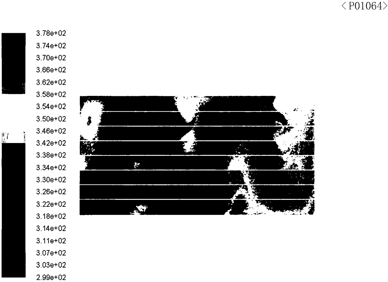
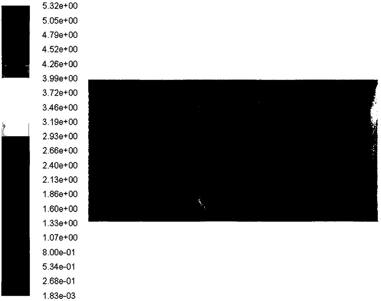
[0043] The flat-plate solar air collector is simulated and analyzed using the same method and parameters as in Example 1, the only difference being that the proportion of the spoiler nozzle on the spoiler is 40%.
[0044] Obtained by CFD software simulation respectively such as Figure 5 The temperature distribution diagram of the heat sink shown as Image 6 The air flow diagram of the flow domain in the housing shown, and the air temperature of the tuyere obtained from the simulation is 62.2 ° C, and the efficiency of the flat-plate solar air collector is 64.28%.
Embodiment 3
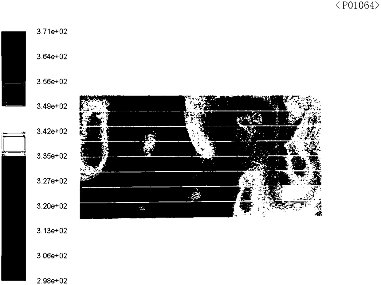
[0046] The flat-plate solar air collector is simulated and analyzed by the same methods and parameters as in Example 1, the only difference being that the proportion of the spoiler nozzle on the spoiler is 80%.
[0047] Obtained by CFD software simulation respectively such as Figure 7 The temperature distribution diagram of the heat sink shown as Figure 8 The air flow diagram of the flow domain in the casing shown, and the air temperature of the tuyere obtained from the simulation is 62.9 ℃, and the efficiency of the flat-plate solar air collector is 64.82%.
PUM
 Abstract
Description
Claims
Application Information
 - R&D Engineer
- R&D Manager
- IP Professional
- Industry Leading Data Capabilities
- Powerful AI technology
- Patent DNA Extraction
Browse by: Latest US Patents, China's latest patents, Technical Efficacy Thesaurus, Application Domain, Technology Topic, Popular Technical Reports.
© 2024 PatSnap. All rights reserved.Legal|Privacy policy|Modern Slavery Act Transparency Statement|Sitemap|About US| Contact US: help@patsnap.com