A pressure forming device and a pressure forming method
A forming device and forming method technology, applied in forging/pressing/hammer device, forging/pressing/hammering machinery, manufacturing tools, etc., can solve the problems of uneven texture of forming workpieces, long blank flow distance, difficult forming, etc. , to achieve the effects of balanced and stable force on the blank material tissue, low cost, and balanced blank material process
- Summary
- Abstract
- Description
- Claims
- Application Information
AI Technical Summary
Problems solved by technology
Method used
Image
Examples
Embodiment 1
[0053] In the description herein, it should be understood that the orientation or positional relationship indicated by the terms "upper", "lower", "inner", "outer", etc. is based on the orientation or positional relationship shown in the drawings, and is only for the convenience of description The present invention and simplified description do not indicate or imply that the device or element referred to must have a specific orientation, be constructed and operate in a specific orientation, and thus should not be construed as limiting the present invention.
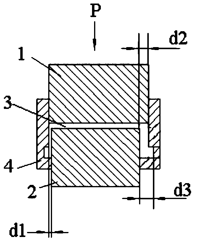
[0054] The preferred embodiment provides a pressure forming device which is mainly but not limited to be used as a swaging device. see figure 2 , the pressure forming device provided in this embodiment includes an upper mold 1, a lower mold 2 and a movable mold 4, the upper mold 1 and the lower mold 2 are relatively arranged and can move relatively, and the movable mold 4 is sleeved outside the upper mold 1 and the lower...
Embodiment 2
[0068] This preferred embodiment provides a pressure forming device, the structure of which is basically the same as the pressure forming device provided in the preferred embodiment 1, the difference is: please refer to Figure 4 and Figure 5 , all sub-lower molds 21 form solid cylinders or hollow cylinders during the pressure forming process. After the pressure forming is completed, driven by the power device, they first move radially outward to make the lower mold expand, and then move radially inward. In order to make the lower mold shrink. The power device that drives the sub-lower mold 21 to move radially is preferably but not limited to a hydraulic cylinder arranged in a direction parallel to the axis of the pressure forming device and connected to the output shaft of the hydraulic cylinder and converts the linear reciprocating motion output by the hydraulic cylinder into Transmission mechanism for radial movement.
[0069] This embodiment also provides a pressure for...
Embodiment 3
[0076] This preferred embodiment provides a pressure forming device, the structure of which is basically the same as the pressure forming device provided in the preferred embodiment 1, the difference is: please refer to Figure 6 and Figure 7 , the lower mold includes at least two fan-shaped sub-lower molds 21 and at least two wedge-shaped sub-lower molds 21, the fan-shaped sub-lower molds 21 and wedge-shaped sub-lower molds 21 are alternately arranged, and all sub-lower molds 21 forms a hollow cylinder during the pressure forming process. After the pressure forming is completed, the wedge-shaped sub-lower mold 21 and the fan-shaped sub-lower mold 21 are driven by the power device to move radially inward in order to make the lower mold shrink.
[0077] This embodiment also provides a pressure forming method based on the above pressure forming device, which is basically the same as the pressure forming method provided in Preferred Embodiment 1, except that:
[0078] The metho...
PUM
 Abstract
Description
Claims
Application Information
 - R&D
- Intellectual Property
- Life Sciences
- Materials
- Tech Scout
- Unparalleled Data Quality
- Higher Quality Content
- 60% Fewer Hallucinations
Browse by: Latest US Patents, China's latest patents, Technical Efficacy Thesaurus, Application Domain, Technology Topic, Popular Technical Reports.
© 2025 PatSnap. All rights reserved.Legal|Privacy policy|Modern Slavery Act Transparency Statement|Sitemap|About US| Contact US: help@patsnap.com


