
Control device for line inrush current

A control device and circuit technology, applied in circuit devices, emergency protection circuit devices, measurement devices, etc., can solve problems such as high hardware requirements, high sampling rate, short-term overload and overvoltage of transformers, etc.

Pending Publication Date: 2018-05-18
大连北方真空开关有限公司
View PDF0 Cites 0 Cited by
  • Summary
  • Abstract
  • Description
  • Claims
  • Application Information

AI Technical Summary

Problems solved by technology

However, if the two situations mentioned above occur, the excitation inrush current increases instantaneously, resulting in a transient process with a duration of several cycles. At this time, the excitation inrush current has little correlation with the short-circuit current.
At the same time, during operation, short-term overload and overvoltage of the transformer occur from time to time
These multiple minor faults and a large number of transient processes will increase the probability of transformer damage
[0006] However, the existing inrush controller installation method often adopts the following two principles, among which the second harmonic braking principle has the following problems: 1. The braking ratio is difficult; 2. It may not be possible to identify the symmetrical inrush current; 3. Modern transformers The change of magnetic lift characteristics reduces the second harmonic content during inrush current, and the protection is prone to malfunction
[0007] Using the discontinuity angle principle to judge will also face some problems: 1. Higher sampling rate is required, so the hardware requirements are higher; 2. Certain measures need to be taken to measure the discontinuity angle after CT saturation

Method used


Image

  • Control device for line inrush current
  • Control device for line inrush current
  • Control device for line inrush current

Examples


Embodiment Construction

[0038] The technical solutions of the present invention will be further specifically described below through the embodiments and in conjunction with the accompanying drawings.

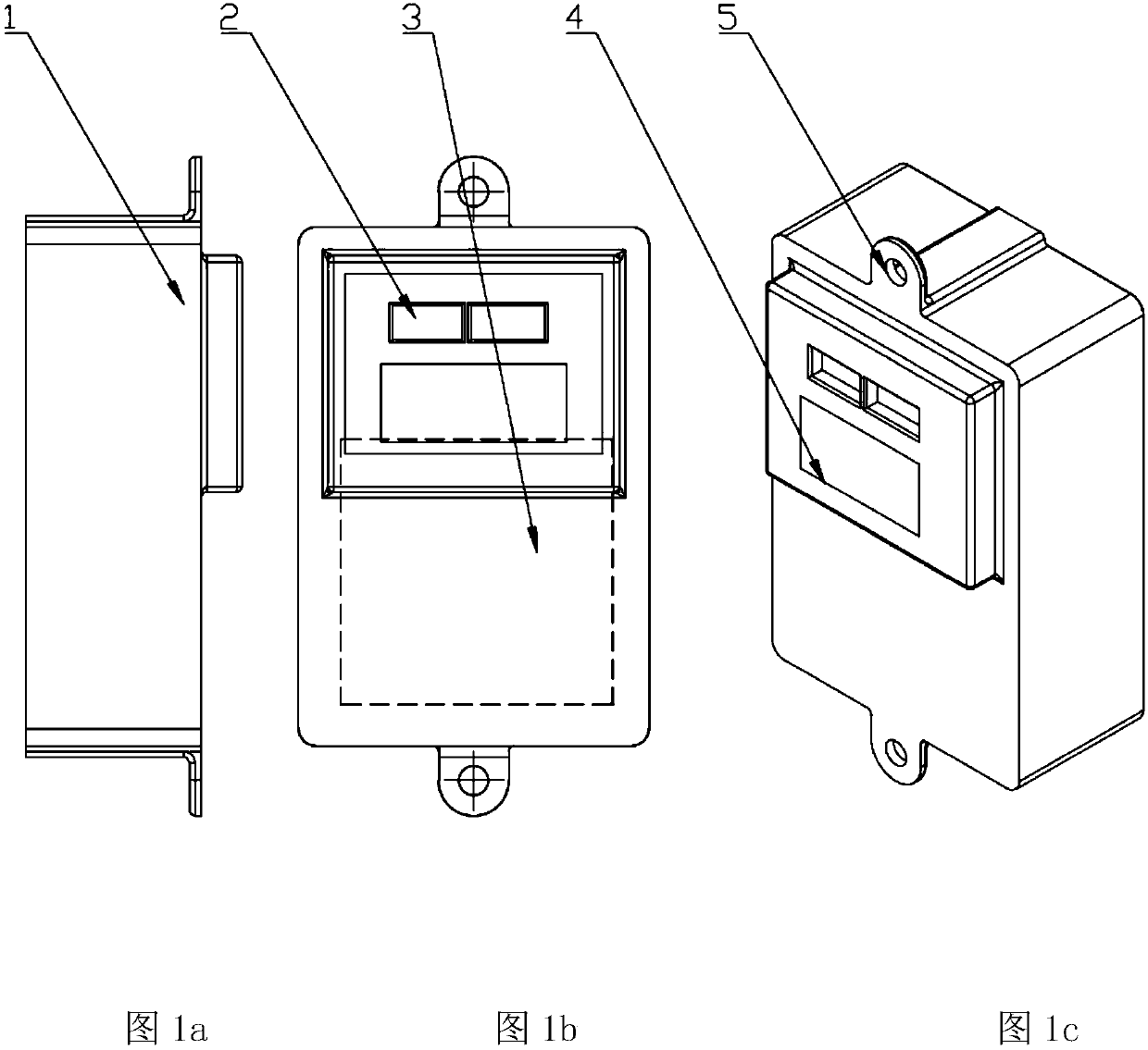
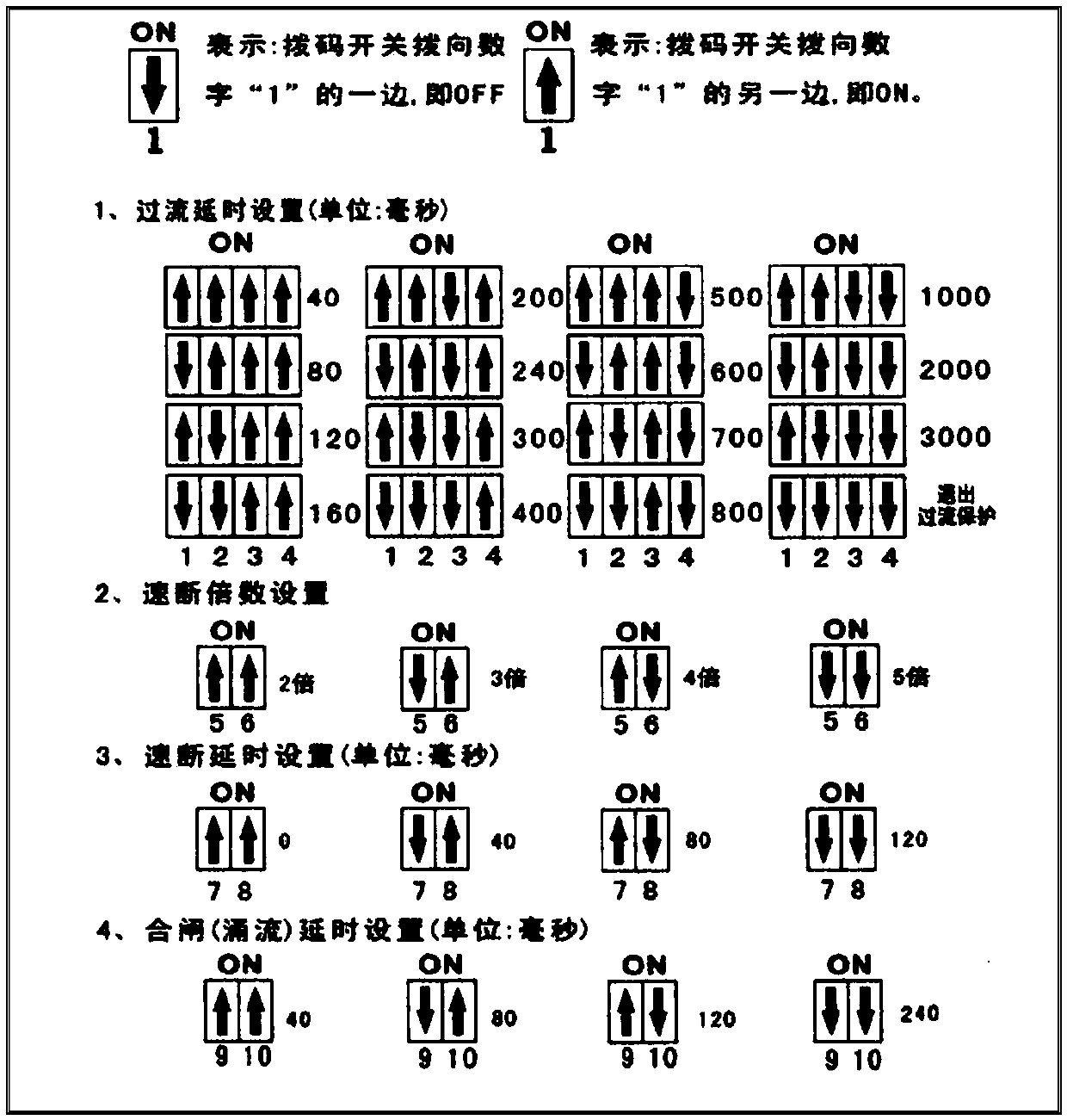
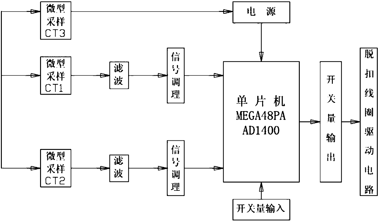
[0039] Embodiment such as Fig. 1, figure 2 , image 3 , Figure 4 , Figure 5 As shown, a line inrush control device includes a housing 1, a dial switch 2, a circuit board 3, a nameplate description 4, and a mounting plate 5. The boss on the housing of the control device is equipped with a setting dial switch 2, which can effectively Ground control inrush current, over-current delay protection, quick break, quick break delay, closing delay, and parameters can be set, using microcontroller technology, when the line current exceeds the multiple setting current set by the dial switch 2 , the circuit board immediately judges and performs quick-break protection, and can also perform delayed operation according to needs.

[0040] The housing is rectangular and made of high-density SMC composite material....


PUM


Abstract

The invention relates to a control device for line inrush current. The control device comprises a casing, wherein a nameplate instruction and a dial switch are arranged above a boss on the front sideof the casing; the dial switch is connected with a circuit board inside the casing through a wire; mounting boards are arranged at the upper end and the lower end of the casing. When a circuit breakeris closed or a power grid is in a working state and exciting current is formed on a line, the control device for the line inrush current can detect line current, delay tripping control and prevent maloperation tripping of the circuit breaker by excitation. By adopting a microcontroller technology, when current exceeds setting current with a set multiple, current properties are immediately judged,and instantaneous over-current protection is performed, and delay duration can be set according to the requirements.

Description

technical field [0001] The invention relates to the technical field of power transmission and distribution, in particular to a line surge current control device matched with a high-voltage circuit breaker. Background technique [0002] In order to achieve long-term uninterrupted power supply, it is necessary to continuously improve the power system and enhance the power supply quality and efficiency of the power system. At the same time, when encountering a fault, the power supply system with a high degree of intelligence can identify the fault as soon as possible and take corresponding protection measures to further protect the equipment. The protection equipment in this power supply system avoids greater losses caused by failures, and develops work efficiency and maintenance costs in the best direction. Nowadays, the development of electronic industry technology is in full swing. Lido large overvoltage transformer was developed and put into production. However, in contr...

Claims


Application Information

Patent Timeline
IPC IPC(8): H02H3/50H02H3/08G01R19/165
CPCH02H3/08H02H3/50G01R19/16571
Inventor 李涛昌徐德成陆振东陈世生刘红赫鑫兰于波隋益先姚昀辰
Owner 大连北方真空开关有限公司
Learn More