Receiving Clamp, Component, Carrying System, And Components Of Receiving Clamp And Working Apparatus

A technology of working equipment and carrying system, applied in the field of accommodating clips, can solve the problems of complicated connection between the guide rod and the carrying system, etc.

Active Publication Date: 2018-05-08
ANDREAS STIHL AG & CO KG
View PDF7 Cites 0 Cited by
  • Summary
  • Abstract
  • Description
  • Claims
  • Application Information

AI Technical Summary

Problems solved by technology

As a result, the connection of the guide rod to the carrying system is complex and consists of several individual parts

Method used


Image

  • Receiving Clamp, Component, Carrying System, And Components Of Receiving Clamp And Working Apparatus
  • Receiving Clamp, Component, Carrying System, And Components Of Receiving Clamp And Working Apparatus
  • Receiving Clamp, Component, Carrying System, And Components Of Receiving Clamp And Working Apparatus

Examples


Embodiment Construction

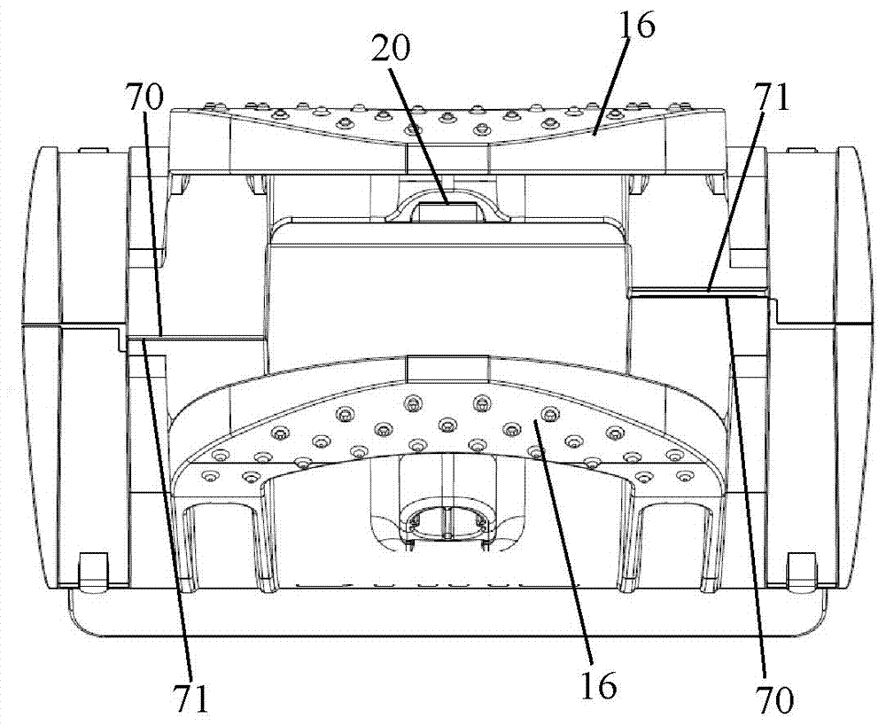
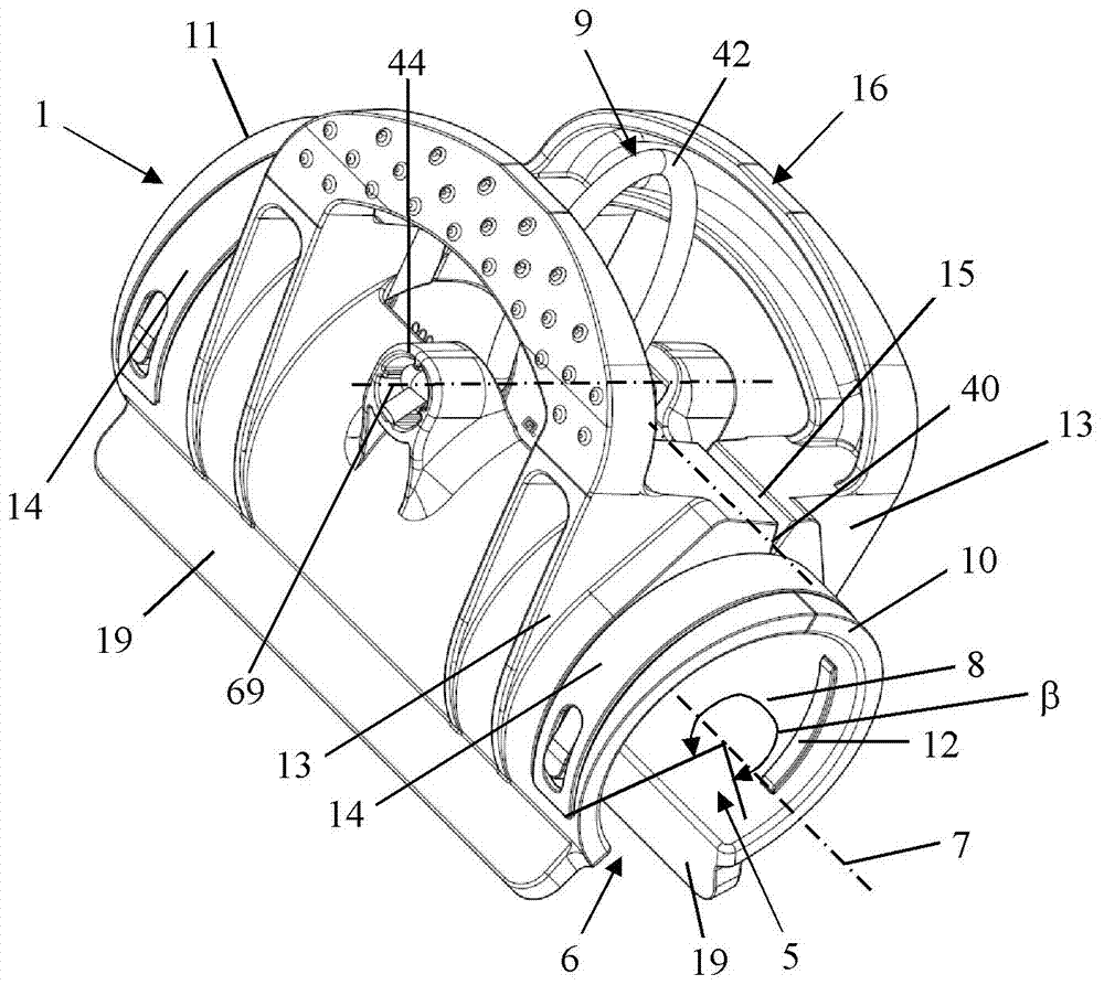
[0046] exist figure 1 An operator 21 is shown in , who uses the carrier system 3 on which the power tool 2 with the guide rod 18 is arranged. The power tool 2 can be, for example, a pruner, a free-cut cutter or another portable power tool 2 with a guide rod 18 . The carrier system 3 is designed to at least partially absorb the weight of the work implement 2 via the shoulders and / or the torso and / or the buttocks of the operator 21 . The carrying system 3 advantageously comprises a carrying plate 22 carried by the operator 21 by means of a waist belt 25 , a back belt 24 and two shoulder belts 23 . The carrying arm 4 is fixed on the carrying plate 22 . The carrying arm 4 protrudes upwards from the operator 21 in the direction of the guide rod 18 of the power tool 2 . In this exemplary embodiment, the first end 27 of the connecting piece 29 is fastened at the protruding end of the carrier arm 4 . The connection piece 29 is in particular flexurally flexible. In this embodiment...


PUM


Abstract

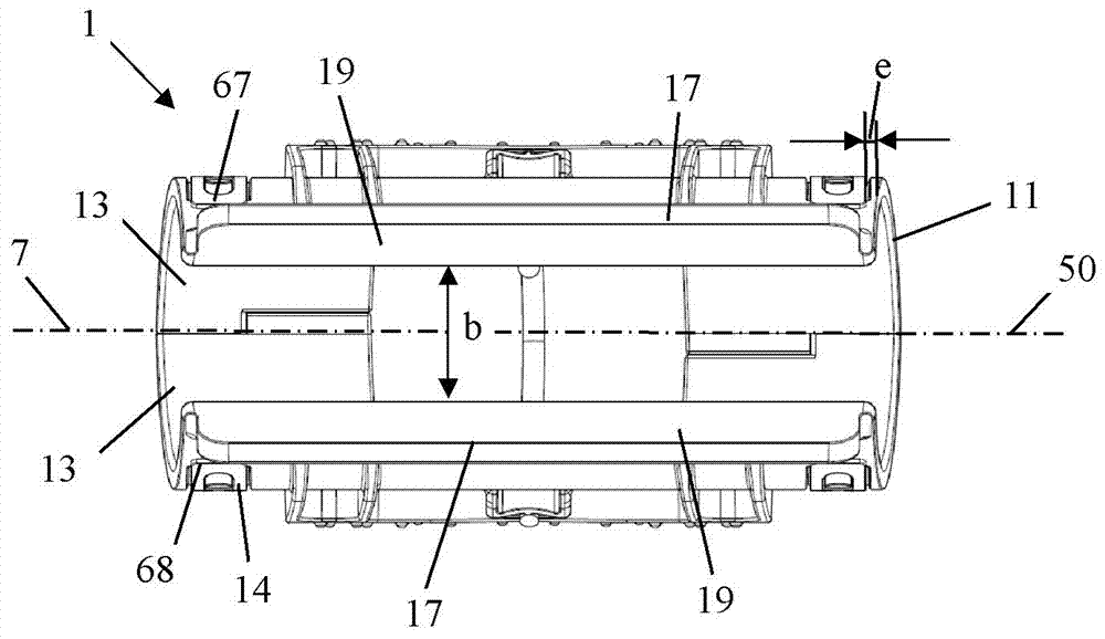
The invention provides a receiving clamp for a power tool. The receiving clamp comprises: a clamp body comprising a first end face and a second end face and a receptacle extending from the first end face to the second end face and configured to receive a guide rod of a power tool; wherein the receptacle comprises a longitudinal center axis and further comprises a slot extending from the first endface to the second end face; wherein the slot is open relative to an environment across an entire length of the slot from the first end face to the second end face; wherein the clamp body comprises abending elasticity in a direction transverse to a length direction of the slot so that the slot can be widened; at least one suspending location arranged on the clamp body and configured to connect toa carrying system for the power tool; wherein the at least one suspending location is arranged such that, when the receiving clamp is suspended by the at least one suspending location and the longitudinal center axis is positioned in a horizontal plane, the slot is located lower than the at least one suspending location.

Description

technical field [0001] The invention relates to a holding clip for a working instrument, an assembly consisting of a carrying system for the working instrument and the holding clip, and an assembly of the carrying system, the holding clip and the working instrument. Background technique [0002] A support system for a power tool with a support arm is known from DE 10 2005 001 843 A1. A receptacle is fastened to the carrier arm, in which a guide rod of the power tool is held. In this case, the receptacle surrounds the shaft of the guide rod and fixes the shaft in the longitudinal direction by means of a clamping force. Due to the elastic configuration of the receptacle, the guide rod can optionally also be displaced in this receptacle. [0003] For a working implement held on the carrying system, the possibility of quickly and easily separating the working implement from the carrying system is desirable as quick release. Such an unloading system is known from EP 1 661 446 ...

Claims


Application Information

Patent Timeline
Patent Type & Authority Applications(China)
IPC IPC(8): F16B7/04F16B2/00
CPCF16B2/00F16B7/0406A45F2003/146A45F2200/0575A01D34/902A45F3/14B25H1/0028A01D34/416A01G3/086A45F2003/142
Inventor P.辛德勒D.扎泽C.巴赖斯J.费伦巴赫S.黑斯
Owner ANDREAS STIHL AG & CO KG
Why Eureka
Try Eureka