A support for annealing soft alloy wire

An alloy wire, annealing technology, applied in the direction of furnace, furnace type, heat treatment equipment, etc., can solve the problems affecting the quality of the wire, and achieve the effect of easy manufacturing, reasonable design and simple structure

Inactive Publication Date: 2018-11-23
WUHU MINTAI COPPER IND
View PDF4 Cites 0 Cited by
  • Summary
  • Abstract
  • Description
  • Claims
  • Application Information

AI Technical Summary

Problems solved by technology

When the weight of a single piece of the product and the elongation and tensile properties of the product are high, since the alloy wire becomes soft after reaching a certain annealing temperature and holding time, the one at the bottom will be pressed out by the one at the top. Indentation, which seriously affects the quality of the wire, in order to solve this problem, an annealing support is urgently needed to ensure that the alloy wire will not have any scratches or indentations when it reaches the M (soft state)

Method used


Image

  • A support for annealing soft alloy wire
  • A support for annealing soft alloy wire

Examples


Embodiment 1

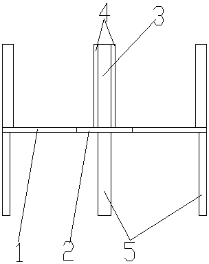
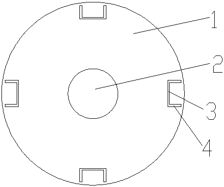
[0018] Such as figure 1 and figure 2 Shown, a kind of support for the annealing of soft state alloy wire rod, it comprises base 1, shaft core 2, frame and inserting plate 5, described base 1 is circular, and its circle center has a circular hole, and inside the circular hole A shaft core 2 matching the diameter of the circular hole is worn, and four frames are vertically fixed at equal intervals on the same side of the circumference of the circular base 1, and the frames include a limiting plate 3 and a supporting plate 4. The limiting plate 3 is an arc vertical plate facing the center of the circular hole, and its two ends are respectively provided with a supporting plate 4 perpendicular to the limiting plate 3 at the center of the circular hole. The plate 4 forms a "ㄩ"-shaped structure; the side of the circular base 1 facing away from the frame is vertically provided with a plug-in board 5 equal to the number of the frame at the corresponding position of the frame, and the...

Embodiment 2

[0023] Same as Example 1, the difference is that three frames are fixed at equal intervals on the same side of the circumference of the circular base 1, which can ensure that the alloy wire becomes soft after the alloy wire reaches a certain annealing temperature and holding time. The lower wires are prevented from being indented by the upper ones, and the quality of the wires is improved, the usage of the frame is minimized, and the cost is reduced.

Embodiment 3

[0025] Similar to Embodiment 1, the difference is that five frames are fixed at equal intervals on the same side of the circumference of the circular base 1, which can improve the overall structural strength of the annealing support.


PUM


Abstract

The invention discloses a soft alloy wire annealing support belonging to the technical field of annealing. The soft alloy wire annealing support comprises a circular base, a shaft core and frameworks, wherein a circular hole is formed in the center of a circle of the base; the shaft core is penetrated into the circular hole; 3-6 frameworks are vertically fixed at the periphery of the circular base at intervals; each framework comprises a limiting plate and supporting plates, wherein the limiting plate is a circular-arc vertical plate, the supporting plates vertical to the limiting plate are respectively arranged at the parts, opposite to the center of the circular hole, of two ends of the limiting plate, and the limiting plate and the supporting plates form a concave structure; and insert plates same as the frameworks in amount are vertically arranged at corresponding positions of the frameworks and at the side, opposite to the frameworks, of the periphery of the circular base. By using the soft alloy wire annealing support, the phenomenon that a wire located at the lower part is pressed by a wire located at the upper part to form a pressing mark can be avoided under the condition that the whole alloy wire becomes soft after reaching to certain annealing temperature and heat insulation time, so that the quality of the wire is improved. The annealing support can also be recycled, so that the production cost is reduced.

Description

technical field [0001] The invention belongs to the technical field of annealing, and more specifically relates to a bracket for annealing soft alloy wires. Background technique [0002] Annealing is a metal heat treatment process, which refers to slowly heating the metal to a certain temperature, keeping it for a sufficient time, and then cooling it at an appropriate speed. The purpose is to reduce hardness, eliminate residual stress, stabilize size, reduce deformation and crack tendency, refine grain, adjust structure and eliminate structure defects. When the weight of a single piece of the product and the elongation and tensile properties of the product are high, since the alloy wire becomes soft after reaching a certain annealing temperature and holding time, the one at the bottom will be pressed out by the one at the top. Indentation, thereby seriously affecting the quality of the wire, in order to solve this problem, an annealing support is urgently needed to ensure t...

Claims


Application Information

Patent Timeline
Patent Type & Authority Patents(China)
IPC IPC(8): C21D9/52C21D1/26
CPCC21D1/26C21D9/52
Inventor 颜承龙
Owner WUHU MINTAI COPPER IND
Why Eureka
Try Eureka