
Sand blasting device for valve body machining

A technology of sandblasting device and valve body, which is applied to used abrasive treatment devices, metal processing equipment, abrasive feeding devices, etc. Conducive to leveling and decoration, avoiding material agglomeration and improving fatigue resistance

Inactive Publication Date: 2018-05-08
新昌县长城空调部件股份有限公司
View PDF0 Cites 3 Cited by
  • Summary
  • Abstract
  • Description
  • Claims
  • Application Information

AI Technical Summary

Problems solved by technology

[0005] Aiming at the deficiencies of the prior art, the present invention provides a sandblasting device for valve body processing, which has the advantage of preventing the clogging of the sand outlet pipe, and solves the problem of material agglomeration due to the transportation and storage of materials. The sand pipe may be blocked, affecting the effect and quality of sandblasting

Method used


Image

  • Sand blasting device for valve body machining
  • Sand blasting device for valve body machining
  • Sand blasting device for valve body machining

Examples


Embodiment 1

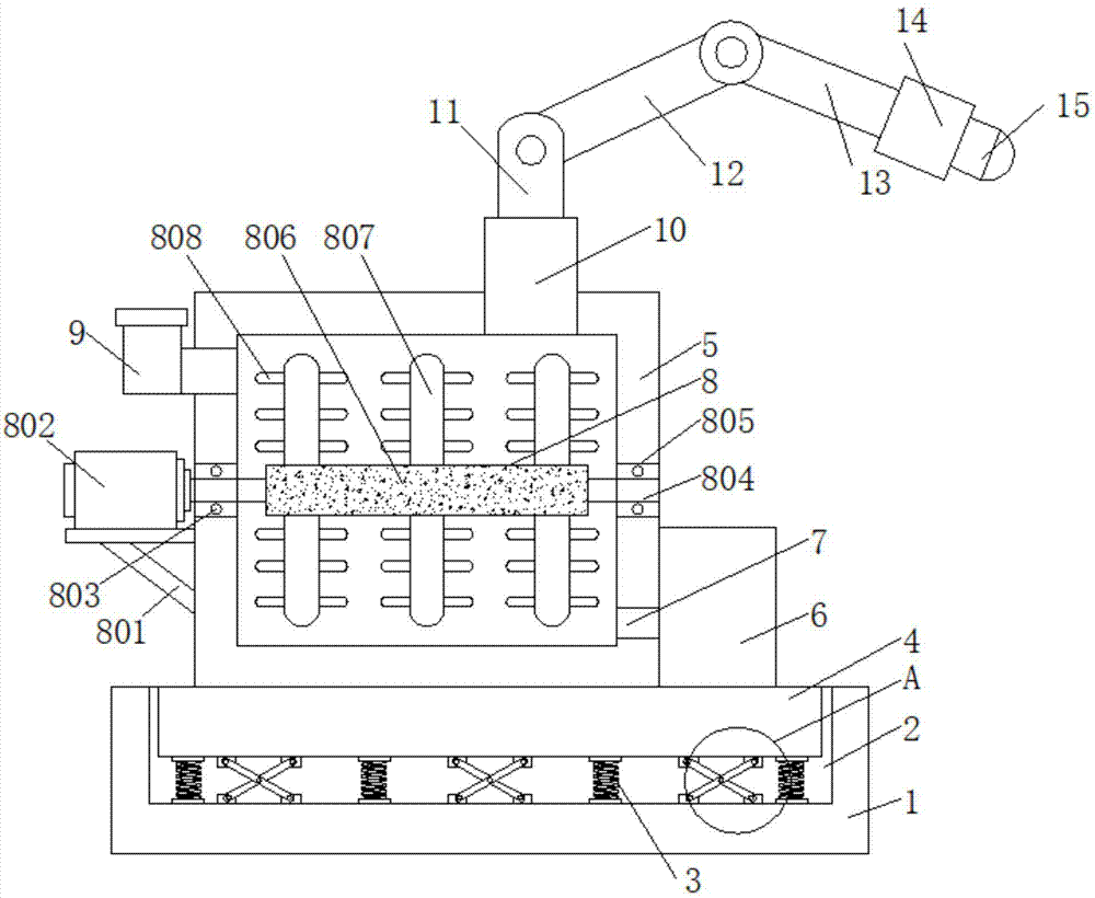
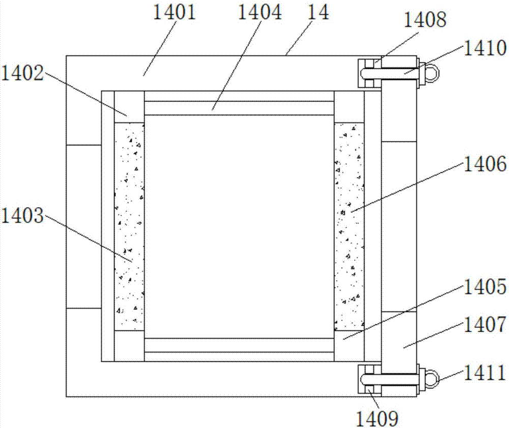
[0030] A sandblasting device for valve body processing, comprising a base 1, a groove 2 is provided in the middle of the top of the base 1, a shock absorbing device 3 is fixedly connected to the inner top wall of the groove 2, and a mounting device 3 is fixedly connected to the top of the shock absorbing device 3 Block 4, one side of the top of the installation block 4 is fixedly connected to the sand storage box 5, and the other side of the top of the installation block 4 is fixedly connected to the air compressor 6, and the exhaust of the air compressor 6 is connected to the sand storage box through the connecting pipe 7. One side of the sand storage box 5 is fixedly connected, and the inside of the sand storage box 5 is provided with a stirring device 8. The top of the sand storage box 5 away from the air compressor 6 is fixedly connected with a feeding hopper 9, and the top of the sand storage box 5 is fixedly connected with a sand outlet. Pipe 10, the top of the sand outle...

Embodiment 2

[0032] A sandblasting device for valve body processing, comprising a base 1, a groove 2 is provided in the middle of the top of the base 1, a shock absorbing device 3 is fixedly connected to the inner top wall of the groove 2, and a mounting device 3 is fixedly connected to the top of the shock absorbing device 3 Block 4, one side of the top of the installation block 4 is fixedly connected to the sand storage box 5, and the other side of the top of the installation block 4 is fixedly connected to the air compressor 6, and the exhaust of the air compressor 6 is connected to the sand storage box through the connecting pipe 7. One side of the sand storage box 5 is fixedly connected, and the inside of the sand storage box 5 is provided with a stirring device 8. The top of the sand storage box 5 away from the air compressor 6 is fixedly connected with a feeding hopper 9, and the top of the sand storage box 5 is fixedly connected with a sand outlet. Pipe 10, the top of the sand outle...

Embodiment 3

[0035] A sandblasting device for valve body processing, comprising a base 1, a groove 2 is provided in the middle of the top of the base 1, a shock absorbing device 3 is fixedly connected to the inner top wall of the groove 2, and a mounting device 3 is fixedly connected to the top of the shock absorbing device 3 Block 4, one side of the top of the installation block 4 is fixedly connected to the sand storage box 5, and the other side of the top of the installation block 4 is fixedly connected to the air compressor 6, and the exhaust of the air compressor 6 is connected to the sand storage box through the connecting pipe 7. One side of the sand storage box 5 is fixedly connected, and the inside of the sand storage box 5 is provided with a stirring device 8. The top of the sand storage box 5 away from the air compressor 6 is fixedly connected with a feeding hopper 9, and the top of the sand storage box 5 is fixedly connected with a sand outlet. Pipe 10, the top of the sand outle...


PUM


Abstract

The invention relates to the technical field of hardware machining, and particularly relates to a sand blasting device for valve body machining. The technical problem to be solved by the invention isblockage on a sand outlet pipe due to material agglomeration. In order to solve the abovementioned technical problem, the invention provides a sand blasting device for valve body machining. The sand blasting device for valve body machining comprises a base, wherein a groove is formed in the middle part of the top of the base; a shock absorption device is fixedly connected to the inner top wall ofthe groove; an installation block is fixedly connected to the top of the shock absorption device; a sand storage box is fixedly connected to one side of the top of the installation block; and an air compressor is fixedly connected to the other side of the top of the installation block. According to the sand blasting device for valve body machining, a rotary shaft is enabled to rotate due to the working running of a motor, and a stirring roll fixedly sleeving the rotary shaft is enabled to rotate, and then a stirring rod and stirring blades are enabled to rotate to crush materials in the sand storage box, so that the problem of blockage on the sand outlet pipe during discharge due to the material agglomeration in material conveying and storage is avoided, and the sand blasting effect is improved.

Description

technical field [0001] The invention relates to the technical field of hardware processing, in particular to a sandblasting device for valve body processing. Background technique [0002] Sand blasting is the process of cleaning and roughening the surface of the substrate by the impact of high-speed sand flow. Compressed air is used as the power to form a high-speed jet beam to spray the spray material (copper ore, quartz sand, corundum, iron sand, Hainan sand) to the surface of the workpiece to be treated at high speed, so that the appearance or shape of the outer surface of the workpiece surface changes. , due to the impact and cutting effect of the abrasive on the surface of the workpiece, the surface of the workpiece can obtain a certain degree of cleanliness and different roughness, so that the mechanical properties of the surface of the workpiece can be improved, thus improving the fatigue resistance of the workpiece, increasing it and coating The adhesion between lay...

Claims


Application Information

Patent Timeline
Patent Type & Authority Applications(China)
IPC IPC(8): B24C3/22B24C7/00B24C9/00
CPCB24C3/22B24C7/0069B24C9/00
Inventor 俞中兴
Owner 新昌县长城空调部件股份有限公司
Learn More