
Multi-flow-path heat exchanger, shunt adjusting method and refrigerant circulating system

A technology of refrigerant circulation system and heat exchanger, which is applied in the direction of fluid circulation arrangement, high-efficiency regulation technology, refrigerator, etc., can solve the problems of lower refrigeration efficiency of the system, too much refrigerant, and high manufacturing cost

Active Publication Date: 2018-05-01
QINGDAO HAIER NEW ENERGY ELECTRIC APPLIANCE
View PDF12 Cites 7 Cited by
  • Summary
  • Abstract
  • Description
  • Claims
  • Application Information

AI Technical Summary

Problems solved by technology

[0004] Although the structures and adjustment methods disclosed in the prior art can accurately control the refrigerant flow ratio of each flow path at the time of design, they have the disadvantages of high manufacturing costs, long time required for structural design and debugging, and when structural design, It can only be debugged based on the rated working condition, and the length of the capillary can only ensure the balance of the heat exchange of each flow path under the rated working condition. The refrigerant in the evaporator will continue to change, and there will be insufficient refrigerant in some flow paths, and there will be too much refrigerant in the other part of the flow path, resulting in an unbalanced refrigerant flow ratio in each flow path of the evaporator, which will cause the evaporator to exchange heat. The area cannot be fully utilized, resulting in insufficient heat transfer of the evaporator and a reduction in the cooling efficiency of the system

Method used


Image

  • Multi-flow-path heat exchanger, shunt adjusting method and refrigerant circulating system

Examples


Embodiment Construction

[0024] Below in conjunction with accompanying drawing and specific embodiment the present invention is described in further detail:

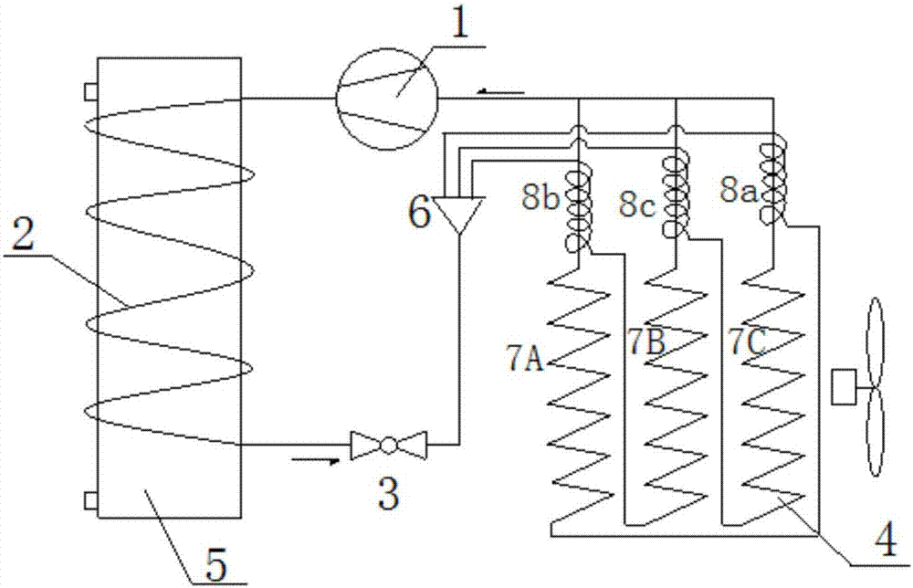
[0025] Such as figure 1 As shown, a refrigerant circulation system provided by the present invention is a heat pump water heater system, including a working medium circulation circuit composed of a compressor 1 , a condenser 2 , a main throttling element 3 and an evaporator 4 . Among them, the main throttling element 3 adopts an electronic expansion valve, which is a first-stage throttling element. The condenser 2 is installed in a water storage tank 5 to exchange heat with the water in the water storage tank 5. The heat of the high-temperature refrigerant working medium heats the water in the water storage tank 5 for use by users. The refrigerant circulation system can also be an air conditioner, refrigerator, freezer and other refrigeration equipment, and only the compressor 1, the condenser 2, the main throttling element 3 and the evaporator...


PUM


Abstract

The invention relates to a multi-flow-path heat exchanger, a shunt adjusting method and a refrigerant circulating system. Throttle elements at inlets of a plurality of flow paths are fixed to the outlet positions of other flow paths in a mutually intersected mode, so that the temperatures of the interiors of the flow paths after working mediums are subjected to heat exchanging are fed back to thethrottle elements of the different flow paths; the throttle elements feel the temperatures of the interiors of the different flow paths after the working mediums are subjected to heat exchanging, andthen the flow of the working mediums in the flow paths which are in series connection with the throttle elements is adjusted; and finally, the outlet temperatures of all the flow paths after the working mediums are subjected to heat exchanging approach to the same. According to the multi-flow-path heat exchanger, dynamic balance of liquid supplying and the heat exchanging ability of all the flow paths in the heat exchanger can be achieved, then freely changed working conditions can be met, and the heat exchanging efficiency and the heat exchanging ability of the heat exchanger are improved.

Description

technical field [0001] The present invention relates to an air-conditioning device, in particular to a multi-flow heat exchanger installed in the air-conditioning device, and at the same time relates to a split-flow adjustment method of the multi-flow heat exchanger and the multi-flow heat exchanger comprising the multi-flow heat exchanger refrigerant circulation system. Background technique [0002] In refrigeration, air conditioning and heat pump hot water equipment, in order to improve the heat exchange efficiency of the evaporator, a multi-flow path structure design is generally adopted, and the low-temperature and low-pressure refrigerant flowing out of the throttling element enters the evaporator from multiple flow paths at the same time Perform heat exchange. [0003] In order to distribute refrigerant to each flow path in the evaporator, a flow divider is installed at the inlet of the evaporator, the inlet of the flow divider is connected to the outlet of the thrott...

Claims


Application Information

Patent Timeline
Patent Type & Authority Applications(China)
IPC IPC(8): F25B41/06F25B41/37
CPCF25B41/34F25B41/37F25B41/31Y02B30/70
Inventor 王建良
Owner QINGDAO HAIER NEW ENERGY ELECTRIC APPLIANCE
Learn More