
Gradually expanding type screw-feed thermal decomposition furnace integrated in vertical shaft flue behind pulverized coal boiler

A pulverized coal boiler and screw feeding technology, which is applied in coke ovens, special dry distillation, energy input, etc., can solve the problems of material crushing, grinding, inability to prevent the entry of outside air, and uneconomical problems, so as to achieve easy grinding Broken, high usable value, high calorific value

Active Publication Date: 2018-04-27
HUAZHONG UNIV OF SCI & TECH
View PDF7 Cites 4 Cited by
  • Summary
  • Abstract
  • Description
  • Claims
  • Application Information

AI Technical Summary

Problems solved by technology

The disadvantages of the prior art are: it needs to use a large amount of electric energy which is a clean energy source, which is uneconomical; its screw mechanism is an auger shape whose radial dimension remains basically unchanged, and it only plays a role in advancing the material to control pyrolysis The effect of the residence time of the material in the furnace cannot be well used to feed and push the biomass raw materials with large particles and high cellulose content and are easy to wind and slender strips of biomass raw materials (such as straw). It can effectively crush and grind materials; it cannot prevent the entry of outside air during the feeding process.

Method used


Image

  • Gradually expanding type screw-feed thermal decomposition furnace integrated in vertical shaft flue behind pulverized coal boiler
  • Gradually expanding type screw-feed thermal decomposition furnace integrated in vertical shaft flue behind pulverized coal boiler

Examples


Embodiment Construction

[0036] The principles and features of the present invention will be described below in conjunction with the accompanying drawings and specific embodiments. The examples given are only used to explain the present invention and are not intended to limit the scope of the present invention.

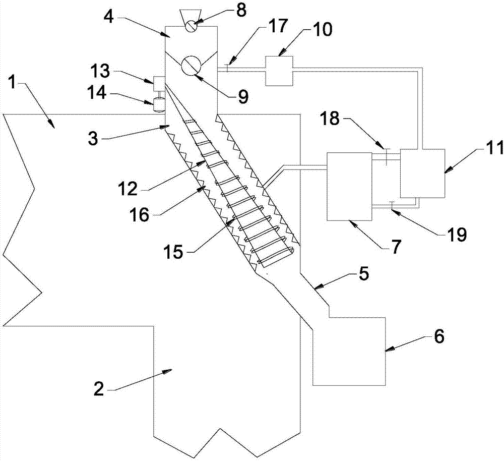
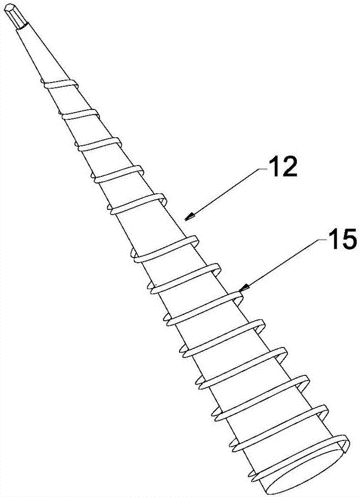
[0037] Such as Figures 1 to 2 As shown, the present invention provides a gradually expanding spiral feed pyrolysis furnace integrated in the rear shaft flue of a pulverized coal boiler, which includes a circular furnace heated at the junction of the horizontal flue 1 and the vertical shaft flue 2 to be heated by the flue gas. A cylindrical furnace body 3, the upper end of the cylindrical furnace body 3 protrudes from the top wall or side wall of the horizontal flue 1 and communicates with the feed chamber 4, and the lower end of the cylindrical furnace body 3 passes through biological The charcoal outlet slideway 5 communicates with the biochar collection bin 6 arranged outside the shaft flu...


PUM


Abstract

The invention relates to a gradually expanding type screw-feed thermal decomposition furnace integrated in a vertical shaft flue after a pulverized coal boiler. The furnace comprises a cylindric furnace body which is arranged at a connecting part between a horizontal flue and the vertical shaft flue; the upper end of the furnace body protrudes from an upper wall or a sidewall of the horizontal flue and is communicated with a feed chamber, and the lower end of the furnace body is communicated with a charcoal collecting bin which is arranged outside the vertical shaft flue through a charcoal outlet slideway; the upper part of a sidewall in the middle area of the furnace body is provided with a tar gas outlet and is communicated with a tar gas condensation bin, and a sidewall at the upper endof the furnace body is provided with a water vapor outlet and is communicated with a combustible gas collecting bin through a water vapor separator; and a spiral pushing arm whose radial dimension isgradually increased from up to bottom along an axial direction is arranged in the furnace body, and the upper end of the spiral pushing arm is connected with a motor in transmission connection through a gear case. The product is advantageous in that the furnace body is inclinedly arranged at a connecting part of the horizontal flue and the vertical flue, in order to effectively utilize waste heatof the flue; the spiral pushing arm with gradually increased radial dimension is arranged in the furnace body, in order to guarantee smooth feeding and effective fragmentation of the raw materials.

Description

technical field [0001] The invention belongs to the field of biomass pyrolysis, and in particular relates to a progressively expanding spiral feed pyrolysis furnace integrated in the rear shaft flue of a pulverized coal boiler. Background technique [0002] China is one of the countries with the most abundant coal resources in the world, and coal power plays an important role in my country's power supply. As of the end of 2016, the installed capacity of power generation in my country reached 1.65 billion kilowatts, of which the installed capacity of coal power was 940 million kilowatts, accounting for 57.3% of the total installed capacity of power generation. The use of pulverized coal furnaces causes a large amount of CO every year 2 emission. CO 2 It is the main greenhouse gas, and its large amount of emission will cause adverse effects on the ecological environment. As the trend of global warming intensifies, reduce the CO of pulverized coal furnace 2 Emissions are u...

Claims


Application Information

Patent Timeline
Patent Type & Authority Applications(China)
IPC IPC(8): C10B53/00C10B57/00
CPCC10B53/00C10B57/005Y02P20/129
Inventor 胡松肖一鸣张雅妮韩亨达向军苏胜汪一许凯江龙张晨浩刘洪佚高建陈小芳
Owner HUAZHONG UNIV OF SCI & TECH
Learn More