Modularized flue gas desulfurization, dust-removing and denitration integrated treatment system

A desulfurization and dust removal and treatment system technology, applied in the direction of gas treatment, chemical/physical process, heterogeneous catalyst chemical elements, etc., can solve the problems of high flue gas flow rate, increased energy consumption, deactivation of denitrification catalyst, etc., to achieve Effects of improving catalyst efficiency, alleviating sulfur poisoning, and improving filtration accuracy

Inactive Publication Date: 2018-04-27
CHONGQING YUANDA CATALYST MFG
View PDF5 Cites 1 Cited by
  • Summary
  • Abstract
  • Description
  • Claims
  • Application Information

AI Technical Summary

Problems solved by technology

With the increasingly stringent requirements of the country for air pollution control in recent years, flue gas desulfurization, denitrification, and dust removal technologies are also constantly innovating. At present, the process flow of desulfurization, denitrification, and dust removal widely used in coal-fired power plants is: plate or honeycomb V-W-Ti system catalyst)—dust removal (by bag dust removal, cyclone dust removal, electric dust removal and other dust removal processes)—wet desulfurization (limestone-gypsum method), but the above three processes operate independently, and the equipment is bulky , and the structure is complex, so the energy consumption is high and the floor area is large
In addition, the traditional process usually puts the SCR denitrification catalyst at the front end of the process. During the long-term operation, the SO in the flue gas 2 , dust, etc. will cause the denitrification catalyst to deactivate, which will greatly affect the life of the catalyst
[0003] The flue gas desulfurization, denitrification and dust removal integrated device and process disclosed in patent CN104667715A mainly have the disadvantages of placing dust removal and denitrification at the front end of the process, and it is difficult to avoid the problem of denitrification catalyst poisoning; fluidized bed denitrification requires high flue gas flow rate, increasing In addition, the dust removal pipe is on the top of the powder denitrification catalyst, so the smoke will enter the denitrification catalyst, affecting the denitrification efficiency
[0004] Patent CN105233644A discloses an integrated composite process system for dust removal, desulfurization and denitrification of coal-fired flue gas, but ceramic tubes and ceramic filter membranes are often used in this process system, and the cost is high, and the process steps are complicated, which is not suitable for wide application

Method used


Image

  • Modularized flue gas desulfurization, dust-removing and denitration integrated treatment system
  • Modularized flue gas desulfurization, dust-removing and denitration integrated treatment system
  • Modularized flue gas desulfurization, dust-removing and denitration integrated treatment system

Examples


Embodiment 1

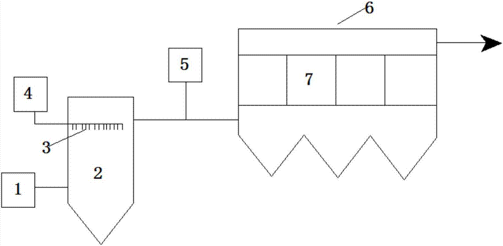
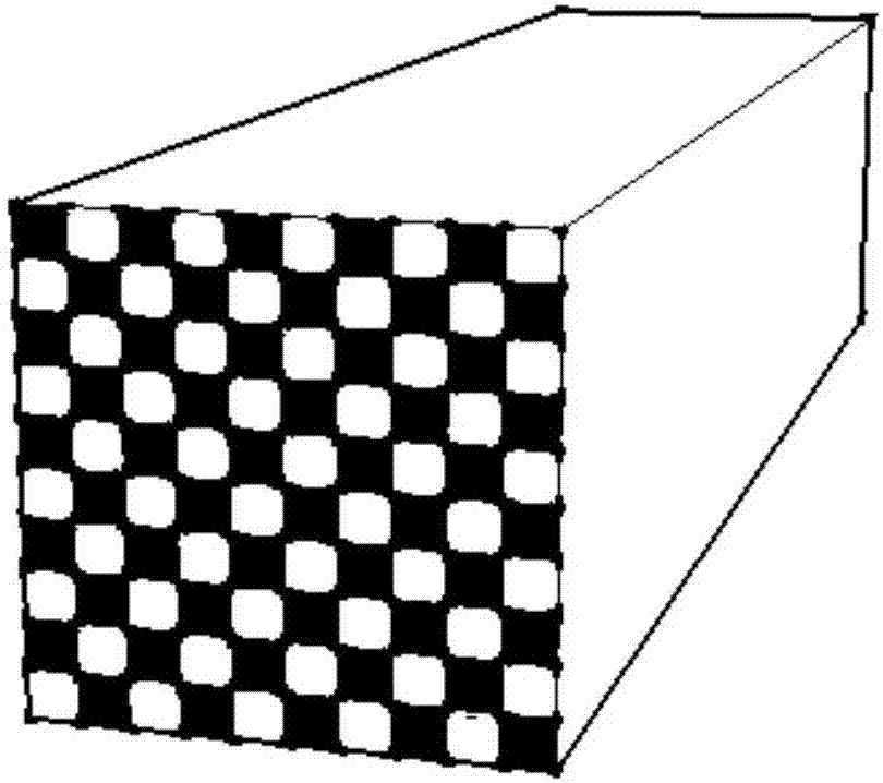
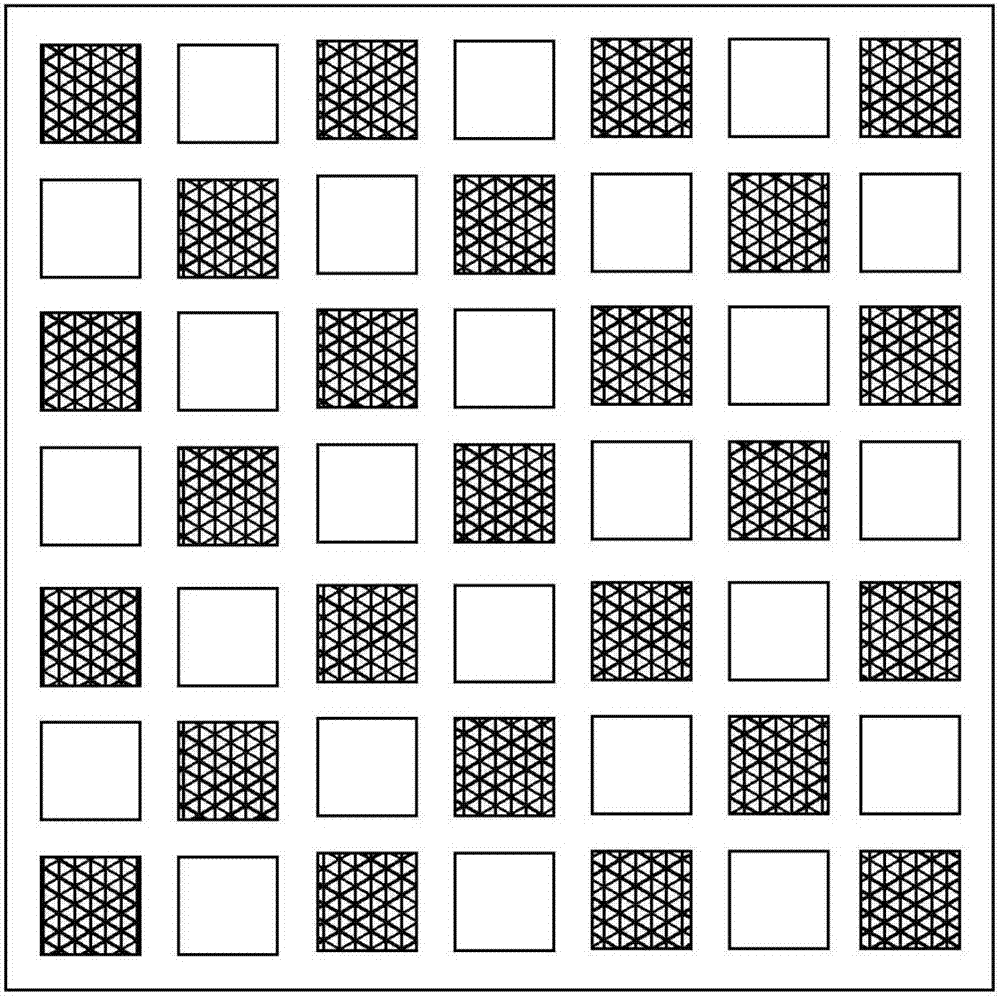
[0035] Catalyst 1 is used as a catalyst unit and assembled into an integrated catalyst module in a matrix arrangement. The three-dimensional schematic diagram of the integrated catalyst module is shown in Image 6As shown, the integrated catalyst module is respectively installed in the reaction chamber 6 of the dust removal and denitrification system in the modular flue gas desulfurization, dust removal and denitrification integrated treatment system, and then the flue gas generated in the boiler 1 is passed into the desulfurization through a closed pipe. In the tower 2, the flue gas is in contact with the calcium oxide sprayed by the nozzle 3 during the flow process, and a large amount of sulfur dioxide reacts with the calcium oxide to realize the removal of sulfur dioxide in the flue gas, and the removal efficiency is above 75%.

[0036] The flue gas after desulfurization treatment enters the reaction chamber 6 through the connecting flue and the ammonia gas sprayed from the ...

Embodiment 2

[0038] Catalyst 2 was used as a catalyst unit and assembled into an integrated catalyst module in a matrix arrangement. Referring to the method in Example 1, the final dust removal efficiency of the treatment system was 99.8%, and the denitrification efficiency was 80.2%.

Embodiment 3

[0040] Catalyst 3 was used as a catalyst unit and assembled into an integrated catalyst module in a matrix arrangement. Referring to the method in Example 1, the final dust removal efficiency of the treatment system was 99.5%, and the denitrification efficiency was 90.6%.


PUM


Abstract

The invention relates to a modularized flue gas desulfurization, dust-removing and denitration integrated treatment system, and belongs to the technical field of flue gas treatment. The system includes a desulfurization system and a dust-removing and denitration system, wherein the dust-removing and denitration system includes a catalyst module formed with a plurality of honeycomb-like V-W-Ti catalysts, of which the two ends are staggered to block holes. In the treatment system, the desulfurization system is located before the dust-removing and denitration system, so that sulfur substances influe gas are removed in a dry desulfurization manner, thereby alleviating a problem of sulfur poisoning of the denitration catalyst. Furthermore, with the catalyst module for dust removal and denitration, the system is high in dust removal and denitration efficiency, is large in filter area and is small in installation size. The system can finally achieve simultaneous dust removal and denitrationat the same time to the flue gas; the catalyst has a honeycomb-like structure, so that compared with conventional tubular ceramic membrane filtering devives, a larger specific surface area is suppliedand usage amount of the catalyst is reduced, thus reducing investment cost; in addition, the honeycomb-like catalysts are assembled in a modularized manner, so that the system is convenient to install on site, and industrialization is easy to achieve.

Description

technical field [0001] The invention belongs to the technical field of flue gas treatment, and in particular relates to a modular integrated treatment system for flue gas desulfurization, dust removal and denitrification. Background technique [0002] The flue gas of industrial kilns, especially coal-fired boilers, contains dust, nitrogen oxides and sulfur dioxide. The above-mentioned flue gas components discharged into the atmosphere will cause a series of air pollution phenomena such as smog and acid rain, thus threatening the ecological environment and human health. With the increasingly stringent requirements of the country for air pollution control in recent years, flue gas desulfurization, denitrification, and dust removal technologies are also constantly innovating. At present, the process flow of desulfurization, denitrification, and dust removal widely used in coal-fired power plants is: plate or honeycomb V-W-Ti system catalyst)—dust removal (by bag dust removal, c...

Claims


Application Information

Patent Timeline
IPC IPC(8): B01D53/50B01D53/75B01D53/86B01D53/56B01J23/30
CPCB01D53/508B01D53/75B01D53/8625B01D2251/2062B01D2251/404B01D2251/602B01D2258/0283B01J23/002B01J23/30B01J2523/00B01J2523/47B01J2523/55B01J2523/69
Inventor 樊永生周林刘显彬段明华段言康平原吴涛王雪冲
Owner CHONGQING YUANDA CATALYST MFG
Why Eureka
Try Eureka