
Laser gas purifying system

A technology of laser gas and exhaust gas, which is applied to lasers, gas treatment, laser components, etc., and can solve problems such as lowering resolution

Inactive Publication Date: 2018-04-17
极光先进雷射株式会社
View PDF8 Cites 2 Cited by
  • Summary
  • Abstract
  • Description
  • Claims
  • Application Information

AI Technical Summary

Problems solved by technology

As a result, the resolution can be reduced

Method used


Image

  • Laser gas purifying system
  • Laser gas purifying system
  • Laser gas purifying system

Examples


Embodiment Construction

[0031] content

[0032] 1. Summary

[0033] 2. Excimer laser device and laser gas refining system of comparative example

[0034] 2.1 Structure

[0035] 2.1.1 Excimer laser device

[0036] 2.1.1.1 Laser oscillation system

[0037] 2.1.1.2 Laser gas control system

[0038] 2.1.2 Laser gas refining system

[0039] 2.2 Action

[0040] 2.2.1 Operation of excimer laser device

[0041] 2.2.1.1 Operation of laser oscillation system

[0042] 2.2.1.2 Action of laser gas control system

[0043] 2.2.2 Operation of laser gas refining system

[0044] 2.3 Topics

[0045] 3. Laser gas refining system including xenon trap

[0046] 3.1 Structure

[0047] 3.2 Action

[0048] 3.3 Processing of Gas Refining Control Department

[0049] 3.4 Supplement

[0050] 3.5 Function

[0051] 4. Laser gas refining system connected with multiple laser devices

[0052] 4.1 Structure

[0053] 4.2 Action

[0054] 4.3 Function

[0055] 5. Laser gas refining system to determine the lifetime of t...


PUM

PropertyMeasurementUnit
boiling pointaaaaaaaaaa
melting pointaaaaaaaaaa

Abstract

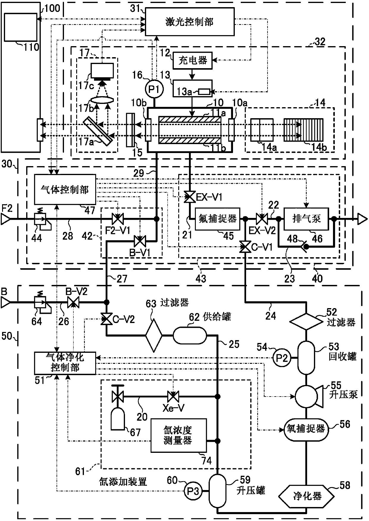
This laser gas purifying system purifies an exhaust gas discharged from an ArF excimer laser device that uses a laser gas containing xenon gas, and supplies the purified gas to the ArF excimer laser device. The laser gas purifying system may be provided with: a xenon trap for reducing the xenon gas concentration of the exhaust gas; and a xenon adding device for adding xenon gas to the exhaust gasthat has passed through the xenon trap.

Description

technical field [0001] The present disclosure relates to laser gas refining systems. Background technique [0002] In recent years, in semiconductor exposure apparatuses (hereinafter referred to as “exposure apparatuses”), improvement in resolution has been demanded along with miniaturization and high integration of semiconductor integrated circuits. Therefore, the shortening of the wavelength of the light emitted from the light source for exposure is progressing. Generally, as a light source for exposure, a gas laser device is used instead of a conventional mercury lamp. For example, as a gas laser device for exposure, a KrF excimer laser device that outputs ultraviolet laser light with a wavelength of 248 nm and an ArF excimer laser device that outputs ultraviolet laser light with a wavelength of 193 nm are used. [0003] As a next-generation exposure technology, liquid immersion exposure in which the gap between the exposure lens on the exposure apparatus side and the w...

Claims


Application Information

Patent Timeline
Patent Type & Authority Applications(China)
IPC IPC(8): H01S3/036B01D53/04B01D53/46B01D53/68
CPCB01D53/04B01D53/685B01D2251/404B01D2251/602B01D2251/604B01D2253/102B01D2253/108B01D2255/20753B01D2255/20761B01D2256/18B01D2257/102B01D2257/104B01D2257/11B01D2257/2027B01D2257/204B01D2257/502B01D2257/504B01D2257/80B01D2258/0216H01S3/036H01S3/08004H01S3/08009H01S3/0971H01S3/104H01S3/134H01S3/2251Y02C20/40B01D2255/50H01S3/1024H01S3/2207H01S3/2232H01S3/225
Inventor 铃木夏志八代将德若林理
Owner 极光先进雷射株式会社
Learn More