Adjustable oil pressure buffer with automatic compensation function

An oil pressure buffer and automatic compensation technology, which is applied in the direction of shock absorbers, shock absorbers, liquid shock absorbers, etc., can solve the problem that the adjustable oil pressure buffer cannot meet the requirements of self-adaptive adjustment, and achieve high rigidity , Strong shock absorbing ability

Active Publication Date: 2018-04-17
C JAC IND CO LTD
View PDF8 Cites 2 Cited by
  • Summary
  • Abstract
  • Description
  • Claims
  • Application Information

AI Technical Summary

Problems solved by technology

[0003] In view of the above problems, the present invention provides an adjustable oil pressure buffer with automatic compensation function, which can solve the problem that the existing adjustable oil pressure buffer cannot meet the requirements of self-adaptive regulation

Method used


Image

  • Adjustable oil pressure buffer with automatic compensation function
  • Adjustable oil pressure buffer with automatic compensation function
  • Adjustable oil pressure buffer with automatic compensation function

Examples


Embodiment 1

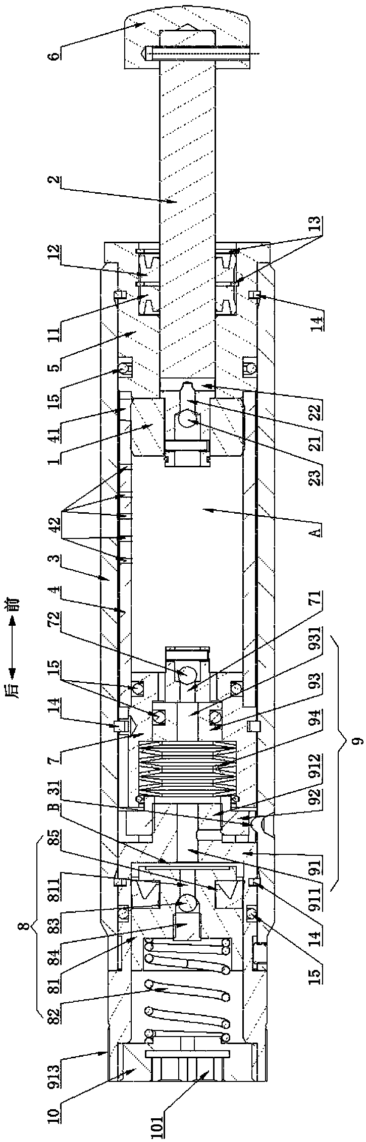
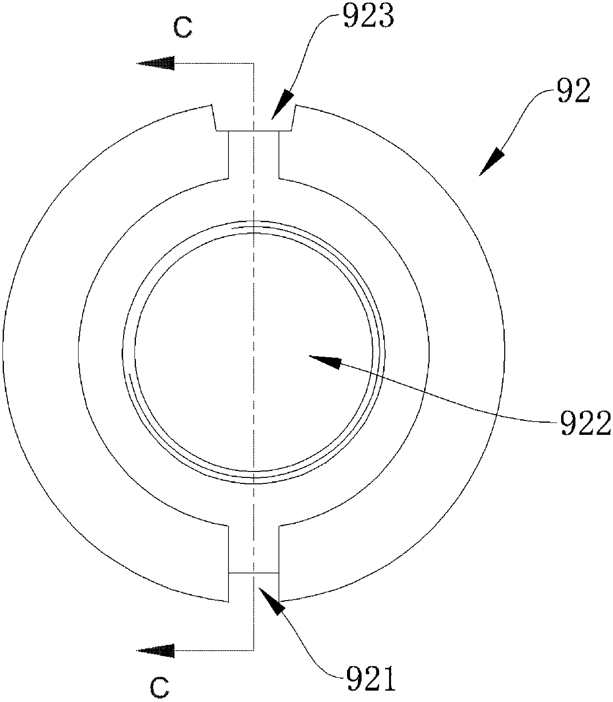
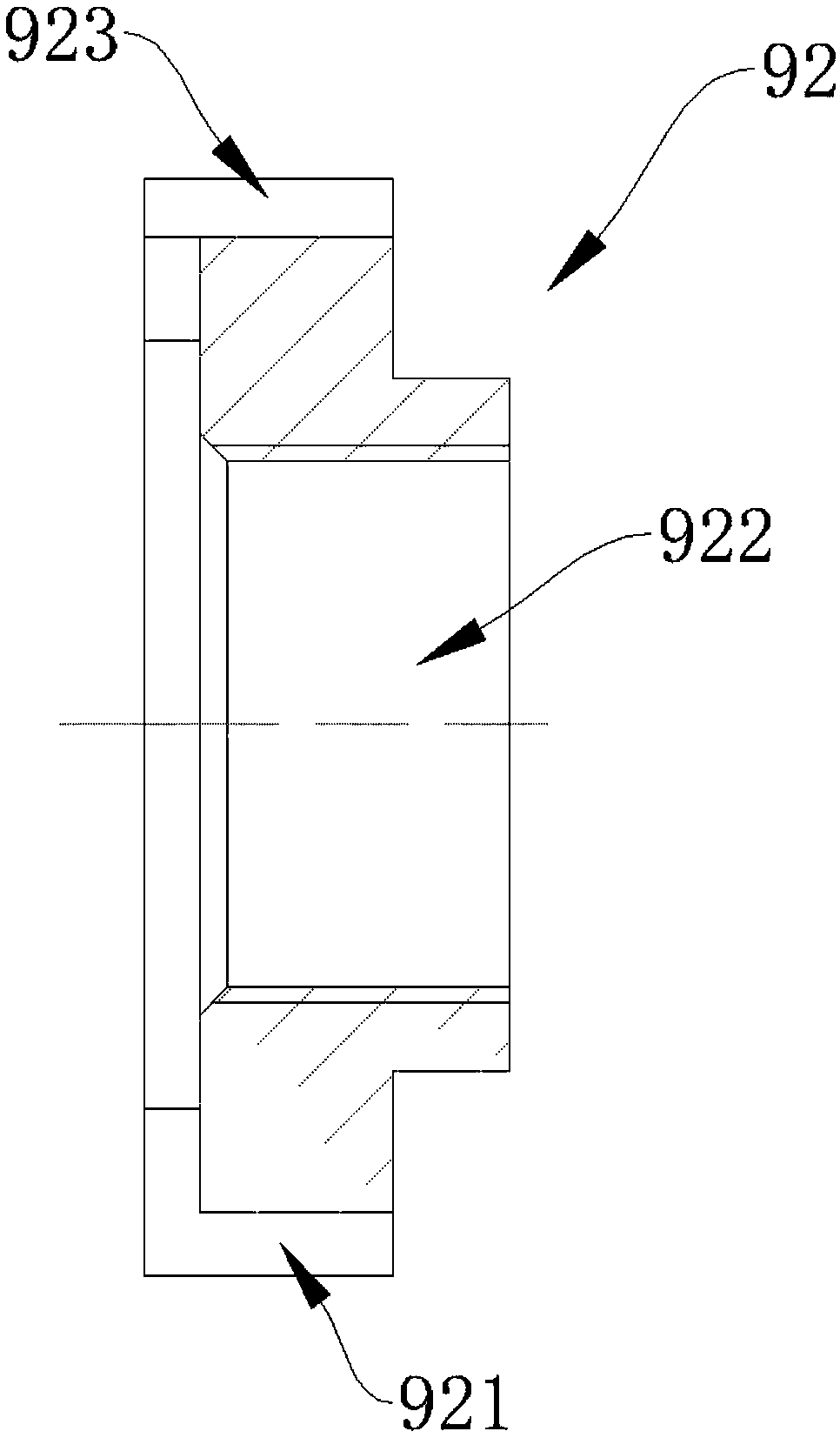
[0041] See figure 1 , figure 2 and image 3 , the present invention has an adjustable oil pressure buffer with automatic compensation function, which includes a piston 1, a piston rod 2, an outer tube 3 and an inner tube 4 set in the outer tube 3, the front end of the outer tube 3 is closed by a bearing 5, The piston 1 is movably installed on the front end side of the inner tube 4, and there is a gap between the outer circumference of the piston 1 and the inner peripheral wall of the inner tube 4. The front end of the piston rod 2 is fixedly connected with the impact head 6, and the rear end passes through the bearing. After 5, it is connected with the piston 1, and the rear end of the inner tube 4 is fixed with a back cover 7, and the inner cavity A formed between the back cover 7 and the piston 1 is filled with hydraulic oil, and the outer tube 3 is provided with a pressure accumulation structure 8. The gap formed between the outer wall of the inner tube 4 and the inner wal...

Embodiment 2

[0053] The difference between the second embodiment and the first embodiment is that an overflow hole 42 is provided on the wall of the inner tube 4. When the piston 1 is pushed by the piston rod 2 and moves toward the front end along the inner tube 4 Squeeze the hydraulic oil in the inner chamber A. When there is a gap between the front end face of the movable block 93 and the front end face 73 of the axially stepped hole of the back cover 7, that is, when the volume of the flow regulating cavity is zero, a part of the hydraulic oil After entering the flow regulating cavity through the flow regulating through hole 74, it enters the accumulator chamber B, and part of it enters the gap between the inner pipe 4 and the outer pipe 3 through the gap between the piston 1 and the inner wall of the inner pipe 4, and then flows into the accumulator chamber B. , and the other part enters the gap between the inner pipe 4 and the outer pipe 3 through the overflow holes 42 one by one and t...


PUM


Abstract

The invention provides an adjustable oil pressure buffer with an automatic compensation function. The adjustable oil pressure buffer can solve the problem that an existing adjustable oil pressure buffer cannot conduct self-adaptation adjustment. A flow adjusting rotary knob is rotationally arranged at the rear end portion of an outer pipe, and an axial step hole concentrically communicating with afirst axial runner is formed in a rear cover. A flow adjusting through hole communicating with the axial step hole is formed in the front end face of the rear cover around the periphery of a first steel ball check valve. A movable stop block is movably arranged in a front end hole of the axial step hole, and a spring assembly is arranged in a rear end hole. A hydraulic oil flow adjusting cavity is formed between the front end face of the movable stop block and the front end face of the axial step hole of the rear cover. The movable stop block is provided with a second axial runner concentrically communicating with the first axial runner, an adjusting ejector sheet is in threaded connection to the front end of the flow adjusting rotary knob and located on the rear end side of an inner pipe, and the front end and the rear end of the spring assembly abut against the movable stop block and the adjusting ejector sheet correspondingly.

Description

technical field [0001] The invention relates to the field of oil pressure buffers, in particular to an adjustable oil pressure buffer with automatic compensation function. Background technique [0002] Oil shock absorbers are energy absorbing components used in the automation industry, which can absorb the kinetic energy of moving objects and make them decelerate smoothly and stop stably. The adjustable hydraulic buffer can adjust the best buffering effect according to the change of the external load condition. It is to set the flow regulating groove inside the hydraulic buffer, and realize the size of the damping force by adjusting the cross-sectional area of ​​the flow regulating groove When the cross-sectional area of ​​the flow regulating groove is larger, the hydraulic oil inside the buffer is easier to pass through the regulating groove, and the buffer damping force is smaller. The damping force becomes larger. However, although the existing adjustable oil pressure b...

Claims


Application Information

Patent Timeline
Patent Type & Authority Applications(China)
IPC IPC(8): F16F9/19F16F9/32F16F9/36F16F9/34
CPCF16F9/19F16F9/3207F16F9/3214F16F9/34F16F9/362
Inventor 王东东
Owner C JAC IND CO LTD
Why Eureka
Try Eureka