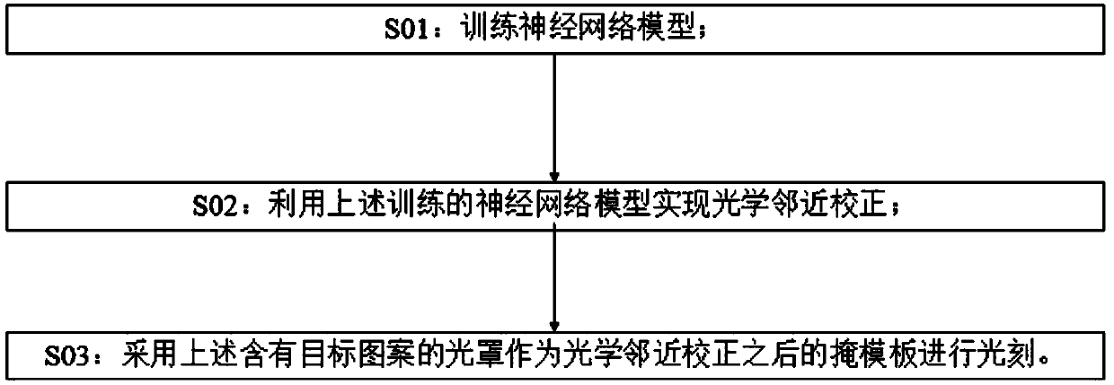
Neural network model-based optical proximity correction method
A neural network model and optical proximity correction technology, applied in the field of optical proximity correction based on neural network model, can solve the problems of increased computing time, impractical full-chip implementation, etc., and achieve the effect of computing improvement
- Summary
- Abstract
- Description
- Claims
- Application Information
AI Technical Summary
Problems solved by technology
Method used
Image


Examples
Embodiment 1
[0057] When the neural network model is a linear neural network model, the required photolithographic mask pattern, that is, the auxiliary pattern and the corrected pattern of the main pattern, can be regarded as at a certain threshold, by cutting a continuous class intensity function and the obtained contour. This class of intensity functions can be derived from the optical image intensity function I(x,y) of the lithographic target pattern via a fixed nonlinear mapping mechanism. Obviously, It not only depends on I(x, y), but also depends on the gray distribution of the optical image intensity function I(x, y) around the (x, y) point. The most efficient way to encode the gray level distribution of the optical image intensity function I(x,y) around the point (x,y) is to use a set of values of the intrinsic imaging signal at the point (x,y). In order to accurately describe the optical image intensity including 3D effects of lithographic masks, the intrinsic imaging signal...
Embodiment 2
[0083] When the neural network model is a quadratic neural network model, as attached Figure 4As shown, the lithographic mask plane is divided into small units, assuming that t(i, j) and t(m, n) are behind the small unit (i, j) and small unit (m, n) lithographic mask light field. Since the response of chemical photoresists is the light intensity, not the light field itself, we can imagine that the target pattern calculated from the reverse lithography technique can be cut by a continuous intensity-like function of and the obtained contour. . This function only depends on all pair values {t(i,j),t(m,n)}, but the function itself is unknown:
[0084]
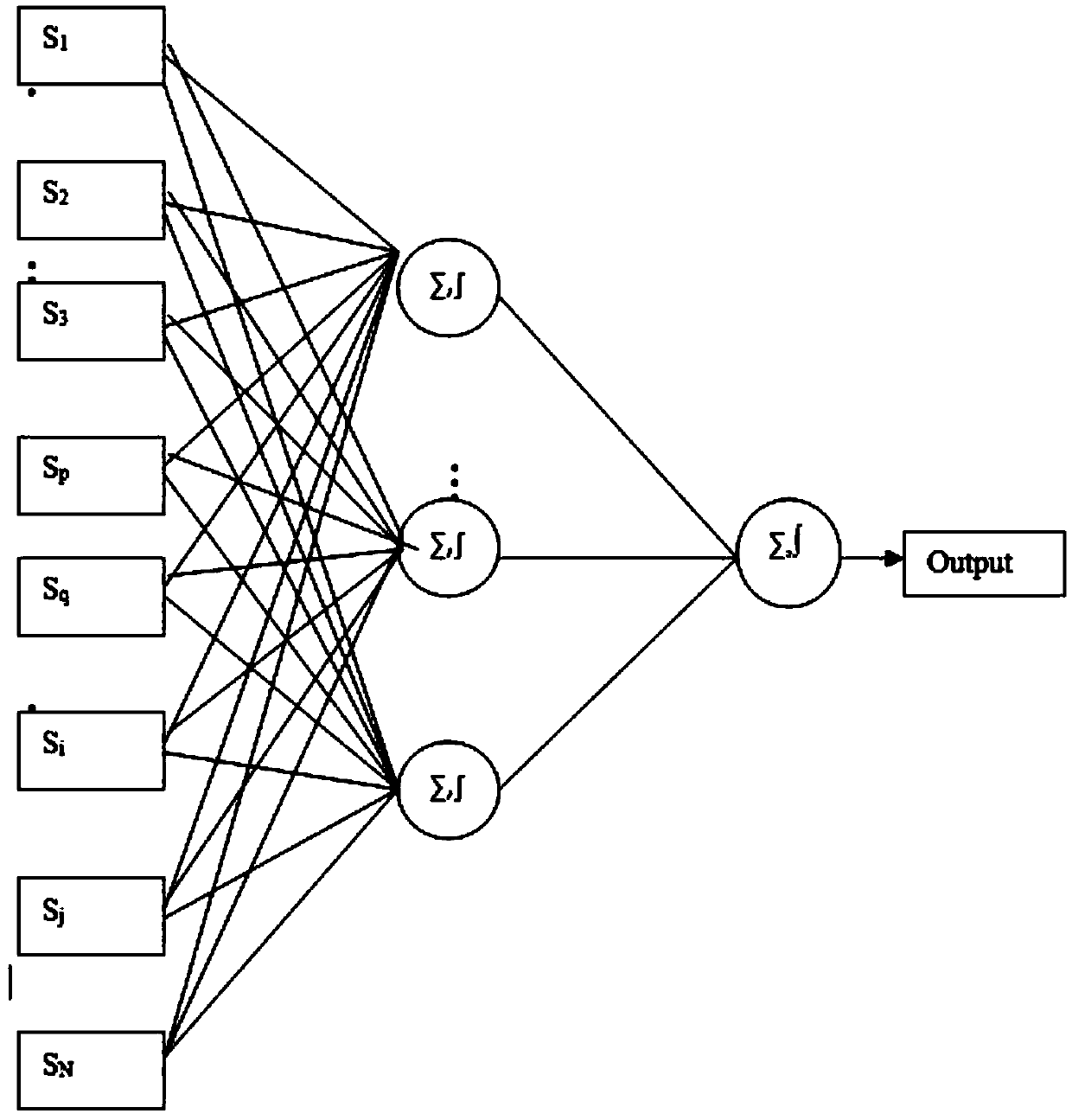
[0085] Pairs {t(i,j),t(m,n)} are defined around the point (x,y). {t(i,j),t(m,n)} are real quantities because all lithography mask types in use today have only phase 0 or phase 180. One way to explore this unknown function is to use a multi-layer perceptron neural network model, with the set {t(1,1)*t(1,1),t(1,1)*t(1,2),...
PUM
 Abstract
Description
Claims
Application Information
 - R&D
- Intellectual Property
- Life Sciences
- Materials
- Tech Scout
- Unparalleled Data Quality
- Higher Quality Content
- 60% Fewer Hallucinations
Browse by: Latest US Patents, China's latest patents, Technical Efficacy Thesaurus, Application Domain, Technology Topic, Popular Technical Reports.
© 2025 PatSnap. All rights reserved.Legal|Privacy policy|Modern Slavery Act Transparency Statement|Sitemap|About US| Contact US: help@patsnap.com