


Quick Research
Generate reliable direction feasibility study reports for your R&D in just a few steps.

Technical Q&A
Discover and master advanced knowledge NOW. Basics, ideas, possibilities, all at once.

Find Solutions
As an expert in R&D theories, this can generate solutions to your technical problems instantly.

Evaluate Feasibility
Analyze your overall solution with one click, know your potential R&D risks in advance.

Monitor Landscape
Get weekly tech updates, stay abreast of the latest tech innovations and key insights.
Liquid Lubrication Method and Cutting Lubrication System Acting on Tool-Swarf Interface
A lubricating system and liquid technology, applied in the direction of tools used in lathes, accessories of tool holders, turning equipment, etc., can solve the problems of short tool life, difficult for lubricant to enter the chip interface, environmental pollution, etc., and achieve the lubrication effect. Good, reduce the temperature of the cutter body, reduce the effect of harm
- Summary
- Abstract
- Description
- Claims
- Application Information
AI Technical Summary
Problems solved by technology
Method used
Image

Examples
Embodiment 1
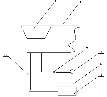
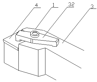
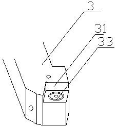
[0028] refer to figure 1 , figure 2 and image 3 , a cutting lubrication system including a cutting tool and a liquid lubricant supply system. Cutter 1 comprises cutter body 4 and cutter bar 3, and cutter bar 3 front end is provided with the knife groove 31 that can place cutter body 4, and cutter bar 3 upper surface is provided with thread fastening hole, and the center of pressing plate 32 is provided with the screw hole that runs through up and down, and pressing plate 32 is screwed into the screw hole and the threaded fastening hole to be connected with the cutter bar 3 by a bolt, and when the pressing plate 32 is fixed on the cutter bar 3 by the bolt, the bottom surface of the pressing plate 32 close to the end of the cutter body 4 is in close contact with the upper surface of the cutter body 4; Inside the tool 1, there is a channel penetrating from the bottom surface of the tool 1 to the tool-chip interface of the tool 1. The upper opening of the channel is located at...
Embodiment 2
[0034] refer to figure 1 , figure 2 and image 3 , a cutting lubrication system including a cutting tool and a liquid lubricant supply system. Cutter 1 comprises cutter body 4 and cutter bar 3, and cutter bar 3 front end is provided with the knife groove 31 that can place cutter body 4, and cutter bar 3 upper surface is provided with thread fastening hole, and the center of pressing plate 32 is provided with the screw hole that runs through up and down, and pressing plate 32 is screwed into the screw hole by a bolt and connected with the threaded fastening hole with the knife bar 3, and when the pressing plate 32 is fixed on the knife bar 3 by the bolt, the bottom surface of the pressing plate 32 close to the end of the knife body 4 is in close contact with the knife body 4;
[0035] Inside the tool 1, there is a channel penetrating from the bottom surface of the tool 1 to the tool-chip interface of the tool 1. The upper opening of the channel is located at the tool-chip in...
Embodiment 3
[0041] refer to figure 1 , figure 2 and image 3 , a cutting lubrication system including a cutting tool and a liquid lubricant supply system. Cutter 1 comprises cutter body 4 and cutter bar 3, and cutter bar 3 front end is provided with the knife groove 31 that can place cutter body 4, and cutter bar 3 upper surface is provided with thread fastening hole, and the center of pressing plate 32 is provided with the screw hole that runs through up and down, and pressing plate 32 is screwed into the screw hole by a bolt and connected with the threaded fastening hole with the knife bar 3, and when the pressing plate 32 is fixed on the knife bar 3 by the bolt, the bottom surface of the pressing plate 32 close to the end of the knife body 4 is in close contact with the knife body 4;
[0042] Inside the tool 1, there is a channel penetrating from the bottom surface of the tool 1 to the tool-chip interface of the tool 1. The upper opening of the channel is located at the tool-chip in...
PUM
 Abstract
Description
Claims
Application Information
 - R&D Engineer
- R&D Manager
- IP Professional
- Industry Leading Data Capabilities
- Powerful AI technology
- Patent DNA Extraction
Browse by: Latest US Patents, China's latest patents, Technical Efficacy Thesaurus, Application Domain, Technology Topic, Popular Technical Reports.
© 2024 PatSnap. All rights reserved.Legal|Privacy policy|Modern Slavery Act Transparency Statement|Sitemap|About US| Contact US: help@patsnap.com