High current-carrying capacity overhead insulation cable and manufacturing technology

An overhead insulated cable, high current carrying capacity technology, applied in insulated cables, power cables for overhead applications, power cables with shielding/conducting layers, etc., can solve the problem that the load cannot be effectively sent to the receiving end and the load channel. It can improve the tensile strength and elongation performance, reduce the occupation pressure, and improve the safety margin.

Pending Publication Date: 2018-04-03
JIANGSU HENGTONG POWER CABLE
View PDF10 Cites 2 Cited by
  • Summary
  • Abstract
  • Description
  • Claims
  • Application Information

AI Technical Summary

Problems solved by technology

Due to the influence of limiting factors such as transmission line corridors, the load channel o

Method used


Image

  • High current-carrying capacity overhead insulation cable and manufacturing technology
  • High current-carrying capacity overhead insulation cable and manufacturing technology
  • High current-carrying capacity overhead insulation cable and manufacturing technology

Examples


Embodiment 1~4

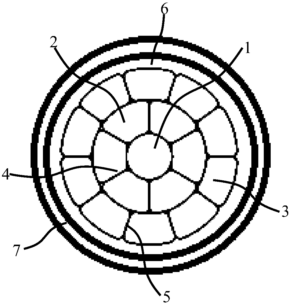
[0038] Embodiments 1 to 4: An overhead insulated cable with high ampacity, comprising: a circular aluminum conductor 1 with high conductivity, several first trapezoidal aluminum conductors 2 and several second trapezoidal aluminum conductors 3, the high conductivity The circular aluminum conductor 1 is located at the center, several first trapezoidal aluminum conductors 2 are twisted on the outer surface of the high-conductivity circular aluminum conductor 1 to form an inner conductive layer 4, and several second trapezoidal aluminum conductors 3 are twisted An outer conductive layer 5 is formed on the outer surface of the inner conductive layer 4, the height of the first trapezoidal aluminum conductor 2 is higher than the height of the second trapezoidal aluminum conductor 3; the outer conductive layer 5 is covered with a semiconductive shielding layer 6, Cross-linked polyethylene insulating layer 7;

[0039] The cross-linked polyethylene insulating layer 7 of the above-menti...

Embodiment 1

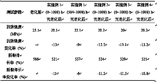
[0051] The properties of the cross-linked polyethylene insulating layer 7 in the overhead insulated cable in Example 1 are shown in Table 2 and Table 3:

[0052] Table 2 The performance change results of the test piece before and after photoaging

[0053]

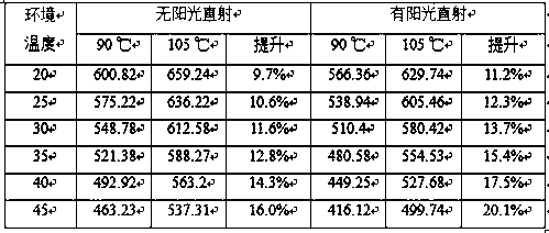
[0054] Table 3 Insulation mechanical properties before and after heat aging

[0055]

[0056] The aluminum rod is characterized in that it adopts a high-conductivity aluminum rod, and its conductivity is increased from 61% IACS of ordinary aluminum rods to 63% IACS. Reduce the loss during line transmission and improve the utilization rate of line power transmission.

[0057] The characteristics of the conductor are: the use of a profiled wire structure reduces the gap between monofilaments, increases the compression coefficient, and better balances the electric field. Compared with the ordinary map structure, under the condition of transmitting the same current, the outer diameter of the conductor of the structure i...


PUM

PropertyMeasurementUnit
Particle sizeaaaaaaaaaa

Abstract

The invention discloses a high current-carrying capacity overhead insulation cable. A semi-conductive shielding layer and a crosslinking polyethylene insulating layer successively wrap an outer conductive layer. The crosslinking polyethylene insulating layer is formed by the following constituents low density polyethylene, high density polyethylene, phosphite ester, bisphenol A, dicumyl peroxide,di-tert-butyl peroxide, trimethylolpropane triacrylate, methacrylate, carbon black,stearic acid, stearin, stearin, ethylene thiourea and texanol. Carbon black is P type and has a particle size of 12-22nm. A sulfur content is 100-500PPM and an ash content is 100-500PPM. The high current-carrying capacity overhead insulation cable meets the demand for a high load, improves a capacity of transmittingcurrent by the overhead cable, can meet demands for tolerable temperature of long time working and a highest operation temperature, guarantee reliability of safe operation, does not cause thermal aging and electric aging insulation faults and thus can realize dynamic capacity increase according to the real time environment for the operation of the cable.

Description

technical field [0001] The invention relates to an overhead insulated cable, in particular to an overhead insulated cable with high ampacity. Background technique [0002] Insulated conductors for 10kV overhead distribution lines are a key link in the construction and renovation of urban distribution networks. It has a series of advantages of buried cables and can overcome many shortcomings of overhead bare wires, and can solve some problems encountered in the operation of conventional bare wires, and the price is much cheaper than buried cables. [0003] With the continuous development of the national economy, my country's electricity demand has shown a sharp increase during the "Twelfth Five-Year Plan" period, especially the power load in the eastern region has continued to increase. With the large-scale construction of UHV power grids, abundant electricity in the west has been continuously transmitted to developed regions in the east. The receiving end of the urban distri...

Claims


Application Information

Patent Timeline
IPC IPC(8): H01B9/00H01B9/02H01B7/29H01B7/28H01B3/44C08L23/06C08K13/02C08K5/524C08K3/04C08K5/09C08K5/103C08K5/405
CPCH01B3/44H01B7/28H01B7/29H01B9/006H01B9/008H01B9/027C08L23/06C08K2201/003C08L2201/08C08L2205/025C08L2203/202C08L2207/062C08L2207/066C08K13/02C08K5/524C08K3/04C08K5/09C08K5/103C08K5/405
Inventor 康慧管新元钱子明虞踏峰原茂标李永志谢卫强
Owner JIANGSU HENGTONG POWER CABLE
Why Eureka
Try Eureka