
A self-protection DC contactor drive circuit

A DC contactor and drive circuit technology, applied in circuits, relays, electrical components, etc., can solve the problems of inconvenient inspection and maintenance, easy disconnection, easy failure, etc., to improve control performance and use safety performance, Extend service life and efficiency, and ensure stable and reliable work

Active Publication Date: 2021-04-02
NORTH CHINA INST OF SCI & TECH
View PDF10 Cites 0 Cited by
  • Summary
  • Abstract
  • Description
  • Claims
  • Application Information

AI Technical Summary

Problems solved by technology

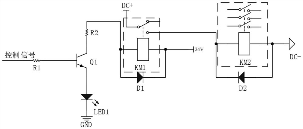
When using this circuit to control multiple high-power DC contactors, multiple intermediate relays are required. This high-power DC contactor circuit can realize its functions, but it brings some problems as follows: (1) The coil of the intermediate relay is relatively small. Thin, prone to disconnection, poor contact contact, and may also cause leapfrog tripping; (2) When the working time is too long, the coil will heat up, which will burn the coil and cause the contact to move randomly; (3) we It is troublesome to choose the appropriate type of intermediate relay, and to manage and maintain the relay in the later stage; (4) There are many and complicated wiring, and it is extremely inconvenient to check and maintain in the later stage; (5) The cost will be greatly increased, and the cost performance Not high; (6) This drive circuit has no protection power and is prone to failure

Method used


Image

  • A self-protection DC contactor drive circuit
  • A self-protection DC contactor drive circuit

Examples


Embodiment Construction

[0012] The embodiments of the present invention will be described in detail below with reference to the accompanying drawings, but the present invention can be implemented in many different ways defined and covered by the claims.

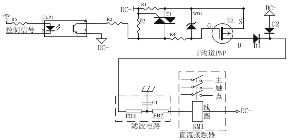
[0013] Such as figure 2 As shown, a self-protection DC contactor driving circuit includes an isolated optocoupler, a bidirectional thyristor, a voltage regulator tube, a MOSFET tube, an anti-reverse diode, a freewheeling diode and a filter circuit, a first resistor, a first voltage dividing resistor, The second voltage dividing resistor and the driving resistor, the first terminal pin of the isolated optocoupler is connected to the positive pole of the power supply through the fifth resistor, and the fourth terminal pin of the isolated optocoupler is connected to the second voltage dividing resistor through the first voltage dividing resistor. One end, one end of the bidirectional thyristor and one end of the drive resistor, the other end of the dr...


PUM


Abstract

The invention discloses a self-protection direct-current contactor driving circuit which comprises an isolation optocoupler, a bidirectional thyristor, a voltage regulator tube, a MOSFET (metal oxidesemiconductor field effect transistor), a reverse-connection-preventive diode, a freewheel diode, a filter circuit, a resistor, a first voltage dividing resistor, a second voltage dividing resistor and a driving resistor. The isolation optocoupler is connected with a positive electrode of a power source by an isolation fifth resistor and is connected with an end of the second voltage dividing resistor, an end of the bidirectional thyristor and an end of the driving resistor by the first voltage dividing resistor. The self-protection direct-current contactor driving circuit has the advantages that high-power direct-current contactors can quickly and reliably work by the aid of the self-protection direct-current contactor driving circuit, and the self-protection direct-current contactor driving circuit has an automatic protection function; the direct-current contactors can reliably work by the aid of the self-protection direct-current contactor driving circuit, stable and reliable work of the direct-current contactors can be guaranteed, the contactors can be prevented from being damaged, the service lives of the direct-current contactors can be prolonged, the use efficiency of the direct-current contactors can be improved, the direct-current contactors are safe for a long term, and the control performance and the use safety performance of the integral direct-current contactors can be improved.

Description

technical field [0001] The invention relates to the field of contactor drive technology, in particular to a self-protection DC contactor drive circuit. Background technique [0002] High-power DC contactor, with its good reliability, airtight structure, stable coil DC power supply and shockproof, is widely used in automobiles, industrial control, especially urban rail transit and railway locomotives. For the control of high-power DC contactor, the control signal is generally used to control the intermediate relay with small voltage and low current, and then the normally open and normally closed contact of the intermediate relay is used to control the opening and closing of the high-power DC contactor coil. Off, this control method requires an additional intermediate relay, and there is no protection, which increases the failure rate and is easy to damage. [0003] as follows figure 1 It is the usual method to control high-power DC contactor at present. Its working principl...

Claims


Application Information

Patent Timeline
Patent Type & Authority Patents(China)
IPC IPC(8): H01H47/00H01H47/32
CPCH01H47/002H01H47/32
Inventor 张全柱邓永红李圆红陈海宇马红梅薛伟宁孙英娟雷旻赵立永
Owner NORTH CHINA INST OF SCI & TECH
Learn More