Self reflecting protective device for firefighting pipeline

A technology for protection devices and fire pipes, which is applied in the direction of valve operation/release devices, valve devices, valve details, etc., can solve the problems of delaying the timing of fire extinguishing in the fire protection system, low accuracy, and long time consumption, and achieve reliable automatic protection. Effect

Pending Publication Date: 2017-08-15
TAIYUAN TAIHANG DIRKSEN FUILD CONTROL TECH CO LTD
View PDF11 Cites 0 Cited by
  • Summary
  • Abstract
  • Description
  • Claims
  • Application Information

AI Technical Summary

Problems solved by technology

[0003] At present, the fault diagnosis of the fire-fighting pipe network mainly depends on empirical judgment and manual search, and then the manual cut-off valve is used to shut off the faulty part of the pipe network to isolate the faulty pipe so that the fire-fighting pipe can continue to run; The method of manual search, judgment and disposal takes a long time, usually more than 20 minutes, but when a disaster occurs, the difficulty of search and processing increases, and the time will be longer, especially when the disaster is severe and the pipe network is severely damaged , the power supply and communication lines are interrupted, the accuracy rate of the manual judgment and processing process will be lower, and the time-consuming will be longer, which may delay the timing of fire extinguishing by the fire protection system and severely damage the safety of life and property.

Method used


Image

  • Self reflecting protective device for firefighting pipeline
  • Self reflecting protective device for firefighting pipeline
  • Self reflecting protective device for firefighting pipeline

Examples


Embodiment Construction

[0017] specific implementation plan

[0018] The present invention will be further elaborated below in conjunction with accompanying drawing:

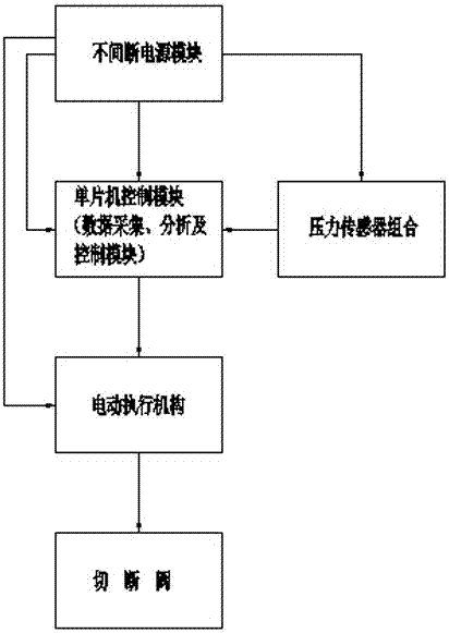
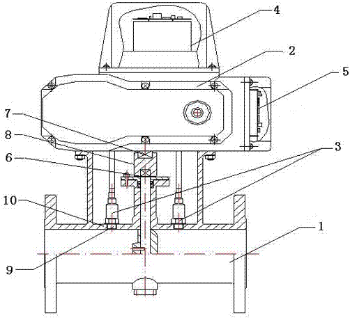
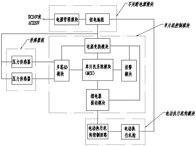
[0019] Such as figure 1 and figure 2 As shown, a self-reflection protection device for fire protection pipelines includes a cut-off valve 1, an electric actuator 2, a pressure sensor group 3, an uninterruptible power supply module 4, and a single-chip microcomputer control module 5; the valve stem 6 of the cut-off valve and the The output shaft 7 of the electric actuator is connected and fixed through the coupling sleeve 8. The pressure sensor group 3 is arranged between the single-chip microcomputer control module 5 and the cut-off valve 1. The measuring end 9 of the pressure sensor group 3 is connected to the valve body of the cut-off valve 1 through a threaded interface. 10 is connected, the transmission output end of the pressure sensor group 3 is connected with the AD conversion module of the single-chip microcomputer control m...


PUM


Abstract

The invention provides a self reflecting protective device for a pipeline. The self reflecting protective device comprises a stop valve, an electric actuating mechanism, a pressure sensor group, an uninterruptible power supply module and a microcontroller control module; the stop valve is connected with the electric actuating mechanism; the pressure sensor group is arranged between the stop valve and the microcontroller control module; a relay of the microcontroller control module is connected with a control circuit of the electric actuating mechanism; and the uninterruptible power supply module is connected with the stop valve, the electric actuating mechanism, the pressure sensor group, and the microcontroller control module and supplies electricity to the stop valve, the electric actuating mechanism, the pressure sensor group, and the microcontroller control module. According to the self reflecting protective device, on the basis that the stop valve is controlled by the electric actuating mechanism, the pressure sensor group and the microcontroller control module are arranged, thus, the stop valve can serve as an actuating mechanism, meanwhile detect the change of pressure in front of and behind the valve and conduct analytical judgment, the device has a independent decision-making function, within seconds when a pipe network is damaged, detecting, judging, decision making and valve stopping can be completed, and the self protecting and alarming functions of the pipe network are achieved.

Description

technical field [0001] The invention relates to a self-reflective protective device for pipelines, in particular to a self-reflective protective device for fire-fighting pipelines. Background technique [0002] The fire-fighting pipeline generally adopts a planar circular main pipe, a vertical straight main pipe, a horizontal connecting pipe and an appropriately arranged shut-off valve to ensure the survivability of the pipeline, so as to realize the supply of fire-fighting water in the case of partial damage to the pipeline, among which The function of the shut-off valve is to isolate the damaged part when there is a significant leakage in the pipeline, so as to avoid the loss of fire water without interrupting the water supply of the fire branch pipe. [0003] At present, the fault diagnosis of the fire-fighting pipe network mainly depends on empirical judgment and manual search, and then the manual cut-off valve is used to shut off the faulty part of the pipe network to i...

Claims


Application Information

Patent Timeline
Patent Type & Authority Applications(China)
IPC IPC(8): F16K31/04F16K37/00
CPCF16K31/041F16K37/005F16K37/0091
Inventor 孙俊强
Owner TAIYUAN TAIHANG DIRKSEN FUILD CONTROL TECH CO LTD
Why Eureka
Try Eureka