A Common Ditch Seismic Isolation System

A Seismic Isolation System, Common Ditch Technology

Active Publication Date: 2019-06-14
福建森正建设集团有限公司 +1
View PDF2 Cites 0 Cited by
  • Summary
  • Abstract
  • Description
  • Claims
  • Application Information

AI Technical Summary

Problems solved by technology

The one-time investment in the construction of the common trench is very high, and if it is destroyed in an earthquake, it will cause serious pipeline damage, supply interruption, and major economic losses

Method used


Image

  • A Common Ditch Seismic Isolation System
  • A Common Ditch Seismic Isolation System
  • A Common Ditch Seismic Isolation System

Examples


Embodiment Construction

[0029] The above and other technical features and advantages of the present invention will be clearly and completely described below in conjunction with the accompanying drawings. Apparently, the described embodiments are only some of the embodiments of the present invention, not all of them.

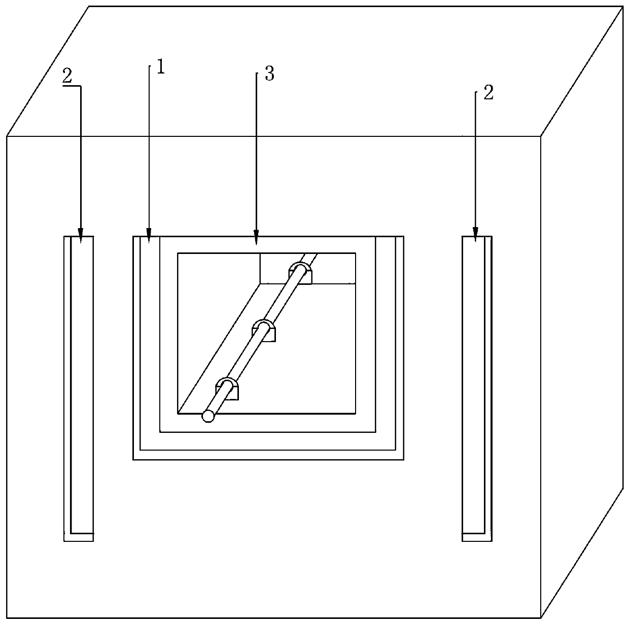
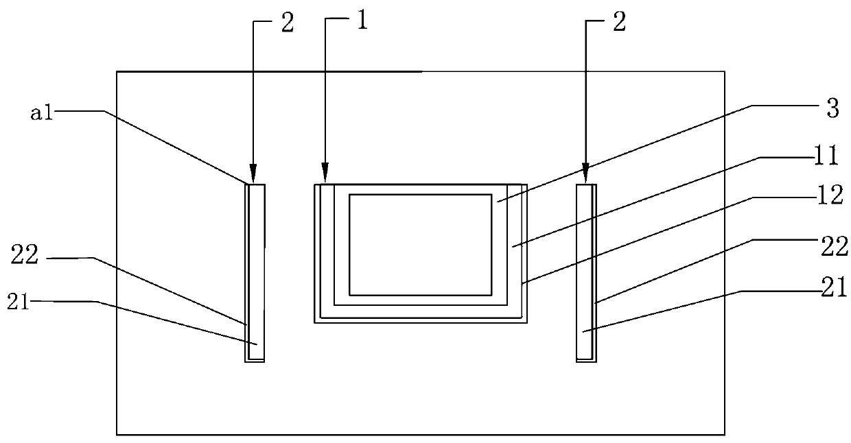
[0030] refer to figure 1 , this embodiment provides a three-dimensional structure arrangement of a common trench isolation system. The common ditch is generally constructed underground by the method of open cut and shallow burial. The cross section of the common ditch concrete layer 3 is generally square, and a few of them are circular or semicircular. , water conservancy, gas and other pipelines or lines. Common ditch concrete layer 3 generally adopts reinforced concrete cast-in-place structure, surrounded by underground soil. In order to counteract the impact of seismic waves, in this embodiment, an outer shock-isolation layer 1 and two-side shock-isolation layers 2 are respectively...


PUM

PropertyMeasurementUnit
particle diameteraaaaaaaaaa

Abstract

The invention provides a utility tunnel shock insulation system which comprises an outer shock insulation layer. The outer shock insulation layer is arranged on the periphery of a utility tunnel concrete layer and is attached to the utility tunnel concrete layer. The outer shock insulation layer comprises a first coarse sand layer and a first asphalt layer, one face of the first coarse sand layeris attached to the utility tunnel concrete layer, and the other face of the first coarse sand layer is attached to the first asphalt layer. One face of the first asphalt layer is attached to the firstcoarse sand layer, and the other face of the first asphalt layer is attached to a soil layer. The sand of the first coarse sand layer is coarse sand with the grain size not smaller than 0.5 mm. The first asphalt layer is a mixture of coal pitch and petroleum asphalt. The large-grain-size coarse sand layer is coarse in surface, and particles have multiple corners. When resultant external force exceeds the maximum static friction force of the coarse sand layer, the coarse sand layer starts to slide, the impact force of an earthquake is consumed, the impact of earthquake waves is greatly consumed, and the coarse sand layer can be prevented from liquefying through the asphalt layer. The outer shock insulation layer covers the two side faces of the utility tunnel concrete layer and the groundsurface in a U shape, and the earthquake waves transferred from the underground and the side faces are prevented well.

Description

technical field [0001] The present invention relates to a seismic isolation system, and more specifically relates to a common ditch seismic isolation system. Background technique [0002] The common trench is a comprehensive corridor of urban underground pipelines. It is a tunnel structure that centrally accommodates various public pipelines installed on the ground, underground or overhead, and leaves a passageway for maintenance personnel. That is to build a tunnel space underground in the city, integrate various pipelines such as municipal, electric power, communication, gas, and drainage, and set up special inspection ports, hoisting ports, and monitoring systems, and implement unified planning, design, construction, and management. It has completely changed the chaotic situation in which each pipeline was constructed and managed separately in the past. When each pipeline needs to be opened, it is only necessary to notify the relevant responsible department and connect t...

Claims


Application Information

Patent Timeline
Patent Type & Authority Patents(China)
IPC IPC(8): E02D31/08E02D29/045F16L3/10F16L3/205
CPCE02D29/10E02D31/08E02D2300/0079E02D2300/0098F16L3/1091F16L3/205
Inventor 王艳茹肖华宁宋廷苏符斌
Owner 福建森正建设集团有限公司
Why Eureka
Try Eureka