
Inverter low voltage riding-through control method for weak network far-end severe voltage failure

A low voltage ride through and voltage fault technology, applied in the field of electrical information, can solve the problems of little research, inverter instability, inapplicability, etc., to improve the stability and dynamic control performance, and solve the effect of overshoot

Active Publication Date: 2018-02-23
ZHEJIANG UNIV
View PDF3 Cites 7 Cited by
  • Summary
  • Abstract
  • Description
  • Claims
  • Application Information

AI Technical Summary

Problems solved by technology

Different from the voltage drop fault at the near-end public connection point in the strong grid, when the voltage drop fault occurs on the remote grid side in the weak grid, the voltage drop at the inverter terminal is small due to the influence of the high inductance value of the line, typically low There may be a risk of inapplicability of the voltage ride-through control strategy, causing new problems of instability in the inverter
[0004] At present, the research on the inverter low voltage ride through process mainly focuses on small disturbance stability analysis and static stability analysis, while the design of inverter system low voltage ride through control methods suitable for remote severe voltage drop faults under weak grid , little research

Method used


Image

  • Inverter low voltage riding-through control method for weak network far-end severe voltage failure
  • Inverter low voltage riding-through control method for weak network far-end severe voltage failure
  • Inverter low voltage riding-through control method for weak network far-end severe voltage failure

Examples


specific Embodiment

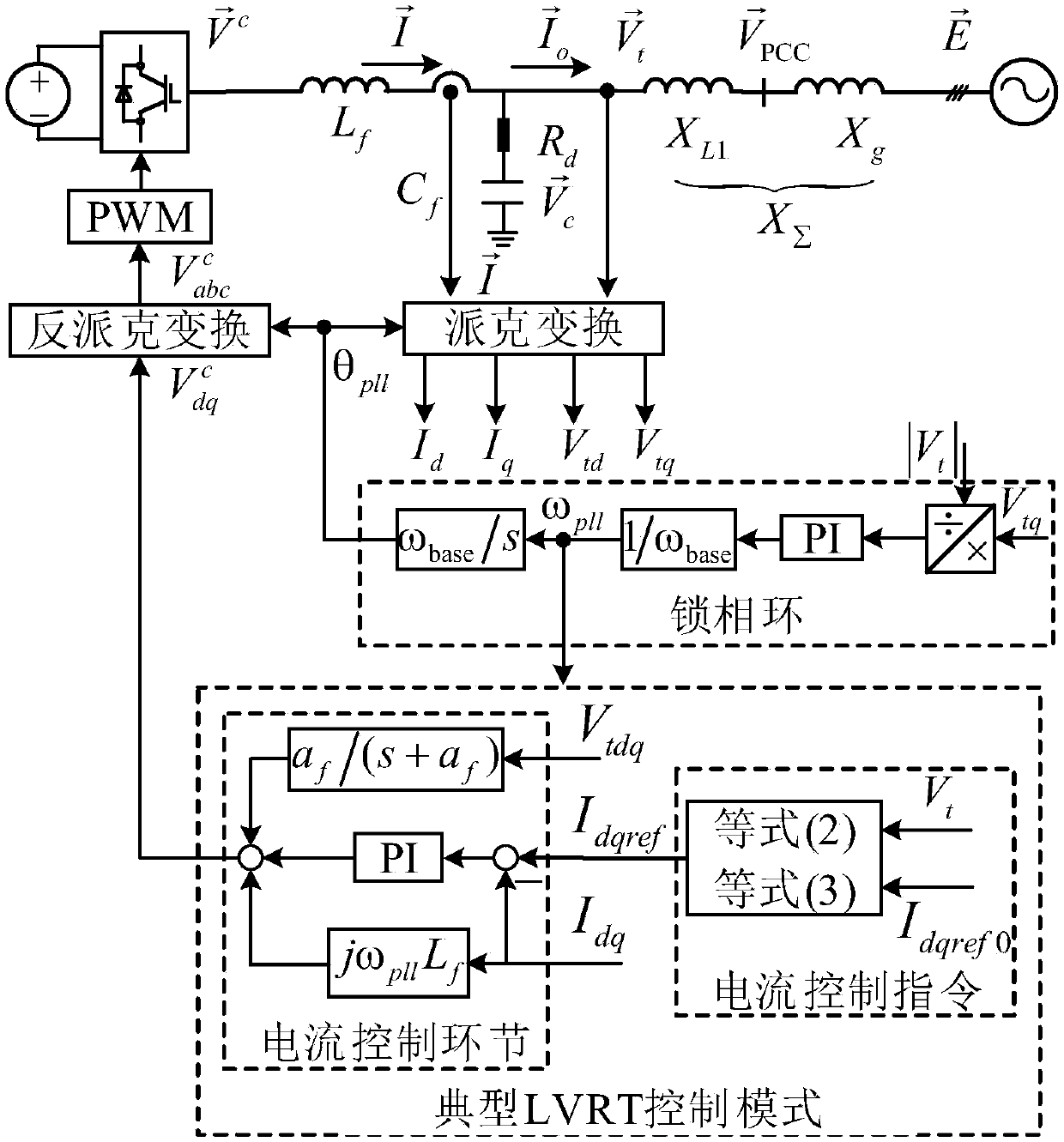
[0094] In order to verify the effectiveness of the proposed control strategy, in the MATLAB / Simulink environment figure 1 The system shown is simulated. The normal control mode of the inverter is "active power / AC voltage" control mode, and the system runs stably at P e = 0.6pu and V t = 1pu, t = 3s when the far-end voltage drop fault occurs. The main parameters are detailed in Table 3.

[0095] Figure 4 Given the line impedance X ∑ =0.8pu, the gain coefficient is k=4, and the voltage drop degree is E=0.2pu, the inverter terminal voltage waveform response curve. Depend on Figure 4 It can be seen that the inverter terminal voltage oscillates up and down around 0.9pu, causing the inverter control mode to switch back and forth between the pre-fault control mode and the typical low-voltage control mode, and the inverter becomes unstable.

[0096] Figure 5 Given the inverter equipped with the low voltage ride through control method proposed by the present invention, the l...


PUM


Abstract

The invention discloses an inverter low voltage riding-through control method for a weak network far-end severe voltage failure. The method comprises the steps of when the weak network far-end severevoltage failure occurs, switching an active current control target quantity and a passive current control target quantity into zero in an inverter, then designing the active current control target quantity and passive current control target quantity input of the inverter, performing transient-state transition, optimizing phase-locked loop, current inner loop and voltage feed-forward parameters, and improving the stability and dynamic control performance of the inverter in low voltage riding-through. According to the inverter low voltage riding-through control method for the weak network far-end severe voltage failure, unstability of the inverter when the severe voltage drop failure occurs at the far end under a weak network can be avoided, the end voltage of the inverter can be effectivelyrecovered, certain active power can be injected into the inverter for supporting the power network frequency, and the method can be applied to achieving low voltage riding-though of an inverter system when the severe voltage failure occurs at a new energy power station grid-connected system far end with the inverter being an interface under the weak network.

Description

technical field [0001] The invention relates to the field of electrical information technology, in particular to an inverter low-voltage ride-through control method for severe voltage faults at the remote end of a weak network. Background technique [0002] As renewable energy such as photovoltaics and wind energy are connected to the power system in large quantities, it is proposed to have low-voltage ride-through capability for renewable energy generation to be connected to the grid at home and abroad. In addition, during the voltage drop period, the grid-connected guidelines require wind farms and photovoltaic power stations to inject reactive current proportional to the voltage drop to support the grid voltage, and the remaining capacity is issued in the form of active power to prevent large active power shortages in the grid And affect the system frequency stability. [0003] Grid-connected guidelines usually take the AC grid as a strong grid (that is, the line inducta...

Claims


Application Information

Patent Timeline
IPC IPC(8): H02J3/38H02J3/48H02J3/50H02J3/16
CPCH02J3/16H02J3/382H02J3/48H02J3/50Y02E40/30
Inventor 袁辉宋美艳辛焕海黄林彬徐璐瑶汪震
Owner ZHEJIANG UNIV
Learn More