Multi-wheel airplane electric brake electromechanical-driven framework and braking force control method

A technology of brake control and drive control, which is applied in the direction of brakes, vehicle components, brake safety systems, etc., and can solve problems such as grade accidents, inability to compensate braking force, safety accidents, etc.

Active Publication Date: 2018-02-02
XIAN AVIATION BRAKE TECH
View PDF3 Cites 0 Cited by
  • Summary
  • Abstract
  • Description
  • Claims
  • Application Information

AI Technical Summary

Problems solved by technology

Through further analysis and research on the architecture of the braking system of the B787 aircraft, it can be seen that the electric braking system of the aircraft still has the following technical defects: when any electric braking power unit 9 or any electromechanical driver fails, resulting in the generation of components When the function of the stage is missing, it will inevitably cause the two wheels on the same side (referring to the left outer, left inner, right inner or right outer) to completely lose the braking ability. At this time, the braking torque on the left and right sides of the aircraft will differ by one It is very easy for the aircraft to deviate from the runway, and even accidents occur; when the two electric brake power units 9 or the electromechanical drives on the left or right side of the aircraft fail at the same time, the aircraft will inevitably deviate from the runway, and accidents are almost inevitable.
[0006] Retrieving related technologies at home and abroad, found that the patents 201410687160.8 "Aircraft Electric Brake System", patent 201410686006.9 "Aircraft Electric Brake System", and patent 201410686233.1 "Aircraft Electric Brake System" applied by Airbus Operations Co., Ltd. The drive control method of the electromechanical brake actuator of the four main brake wheels of the aircraft. These patents use the left and right electromechanical drivers of the electric brake to independently brake the left and right wheels of the aircraft. Like the B787 aircraft, its common defect is that when the left or right electric brake driver or power supply unit fails at the same time, it will cause the flight brake to deviate and cause a safety accident; in addition, the patent US 9376093B2 "Brake System Autonomous Enabling System and Method" has a schematic diagram of the electric brake system for an aircraft with four main brake wheels. From the analysis of the figure, it can be seen that it controls the inner and outer sides of the aircraft through two electric brake drivers. The two wheels are independently braked and controlled. This kind of drive control scheme for the electromechanical actuator of the aircraft electric brake system will not cause the flight brake to deviate when the inner or outer electromechanical driver fails. From this point of view , is improved compared to the previous technology, but the braking capacity of the aircraft will be reduced by half, and when the two electric brake drives fail, the aircraft will completely lose the braking capacity; moreover, the existing electric braking system fails when a single electromechanical drive At this time, the compensation of the braking force cannot be carried out, because even if the two main brake wheels in normal operation have the ability to absorb all the braking energy of the aircraft, the control system cannot simply pass the power to the other two main brake wheels that are still in normal state. Increase the brake pressure to keep the braking distance from extending. This is because the vertical load distributed to the normal wheels by the aircraft remains unchanged, and the maximum braking resistance that the runway can provide to the normal wheels does not increase. When the braking torque received is greater than the maximum frictional resistance torque that the wheel can provide, the wheel will brake quickly, and during the process of wheel braking, the frictional resistance provided by the ground will continue to decrease. In order to prevent the wheel from braking , the anti-skid system is bound to work to reduce the brake pressing force of the electromechanical actuator on the brake disc, and then apply the brakes after the wheel resumes rotation. Because of this, simply increasing the brake pressing force of the normal wheel will inevitably Cause the wheels to slip, the frequent work of the anti-skid system will not only fail to improve the braking ability of the aircraft, but will prolong the braking distance
Therefore, simply trying to compensate for the loss of braking ability by greatly increasing the braking force of the electromechanical actuator on the other side of the wheel that can work normally is not feasible.

Method used


Image

  • Multi-wheel airplane electric brake electromechanical-driven framework and braking force control method
  • Multi-wheel airplane electric brake electromechanical-driven framework and braking force control method
  • Multi-wheel airplane electric brake electromechanical-driven framework and braking force control method

Examples


Embodiment 1

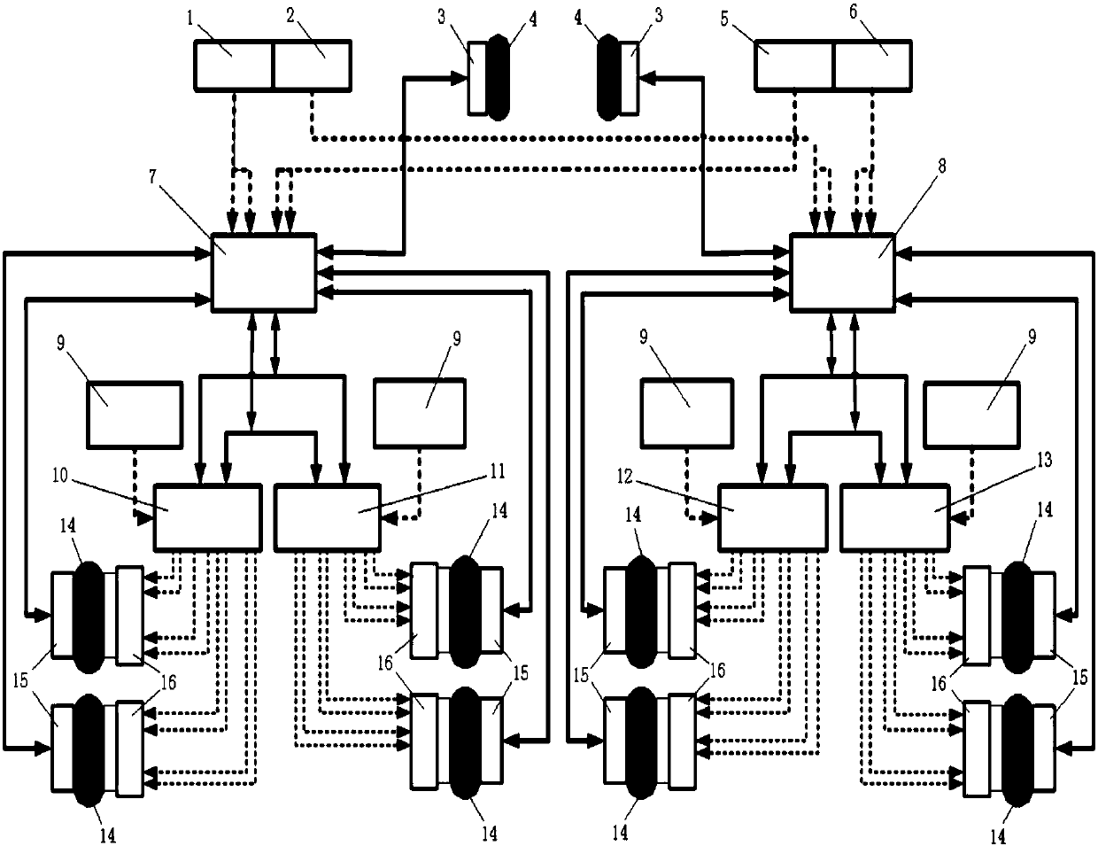
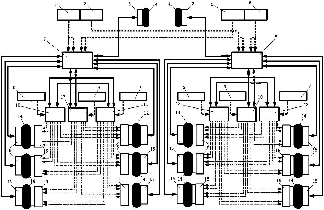
[0053] The present embodiment is a multi-train aircraft electric brake control and monitoring system based on twelve main brake wheels of a certain large aircraft. The left and right sides of described aircraft respectively have the main landing gear of the three struts of front, middle and rear three rows of a group, two wheels are horizontally installed on the axle of each strut, so the main landing gear of every side There are 6 main brake wheels 14, each main brake wheel 14 has a brake device 16 and a main wheel remote data concentrator 15, and four identical electromechanical devices are evenly distributed in the circumferential direction of each brake device end face. Actuator, so that there is a uniform braking pressure between the brake disc and the static disc surface, ensuring the stability of the braking torque and the uniform wear of the disc surface.

[0054] This embodiment includes a command control framework and a drive control framework.

[0055] The command ...

Embodiment 2

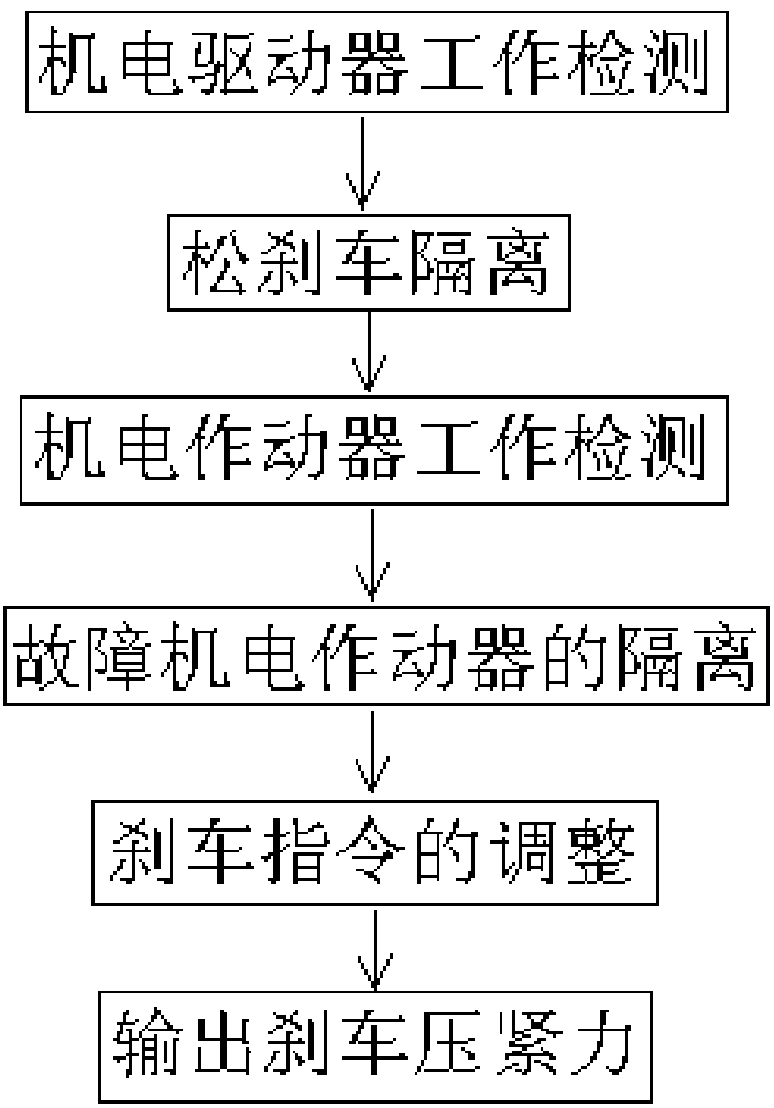
[0073] In this embodiment, when one or more of the electric brake power supply unit, the electromechanical driver, and the electromechanical actuator of the aircraft's brake control and monitoring system fails, the above-mentioned multi-wheel train aircraft electric brake electromechanical drive architecture The method for realizing braking force control, the specific process is:


PUM


Abstract

Provided are a multi-wheel airplane electric brake electromechanical-driven framework and a braking force control method. Six electromechanical drivers on a left undercarriage and a right undercarriage are arranged on the left side and the right side separately, every two of electromechanical actuators are crossed and combined in the longitudinal direction to form six electromechanical actuator sets according to the positions, including the front portion, the middle portion and the rear portion, in a wheel system, and the electromechanical actuator sets are controlled by the different electromechanical drivers correspondingly. When the electromechanical drivers or an electric braking power unit is broken down, an electric braking system performs isolation on relevant electromechanical drivers through a braking controlling / monitoring unit; and the braking controlling / monitoring unit detects the operation of the electromechanical actuators and isolates the broken-down electromechanical actuators from other electromechanical actuators independently, the loss of total braking force caused by the broken-down actuators on wheels can be compensated for by increasing the braking command ofthe electromechanical actuators capable of operating normally, the braking efficiency of the electric braking system of an airplane is improved, and the safety of the braking process of the airplaneis ensured.

Description

technical field [0001] The invention belongs to the field of electromechanical actuator control in aircraft brake system engineering, and in particular relates to the improvement of the electromechanical drive structure of multi-wheel train aircraft electric brakes. Background technique [0002] The aircraft electric braking system uses electric energy as a power source to control the braking force acting on the aircraft wheels according to the braking command imposed by the pilot. [0003] Boeing's B787 aircraft is currently the most advanced electric brake system, using electromechanical actuation and drive control technology. figure 1 It is the structural principle diagram of the brake control and monitoring system of B787 aircraft, mainly including one captain left brake command sensor 1 and one captain right brake command sensor 2, two front wheel remote data concentrators 3 and two front wheel 4, One chief pilot left brake command sensor 5 and one chief pilot right br...

Claims


Application Information

Patent Timeline
IPC IPC(8): B60T8/17B60T13/74B60T17/22
Inventor 张谦张颖姝
Owner XIAN AVIATION BRAKE TECH
Why Eureka
Try Eureka