
A Method of Using Cartridge Logic Valve to Realize Hydraulic Control of Pulling and Straightening

A logic valve and plug-in technology, which is applied in the direction of fluid pressure actuators, servo motor components, mechanical equipment, etc., can solve the problems of small diameter of plate valve parts, large tension and straightening hydraulic system, and slow response speed. Achieve the effects of reduced structure, less internal leakage and high reliability

Active Publication Date: 2019-04-05
河北张宣高科科技有限公司
View PDF11 Cites 0 Cited by
  • Summary
  • Abstract
  • Description
  • Claims
  • Application Information

AI Technical Summary

Problems solved by technology

At present, the hydraulic control of the stretching and leveling machine mainly adopts the continuous casting of integrated blocks and plate valves for control, so that the hydraulic control valve group of the stretching and leveling machine will be made very large. development, especially the emergence of ten-machine ten-stream and twelve-machine twelve-stream continuous casting machines, the hydraulic system of tensioning and leveling using the original continuous casting machine tensioning and leveling hydraulic control method is bound to be very large, and the plate valves are generally used The diameter is not large, the flow rate is small, and the response speed is slow. The existing hydraulic control method of the tension leveler cannot adapt to the development of continuous casting technology.

Method used


Image

  • A Method of Using Cartridge Logic Valve to Realize Hydraulic Control of Pulling and Straightening
  • A Method of Using Cartridge Logic Valve to Realize Hydraulic Control of Pulling and Straightening

Examples


Embodiment Construction

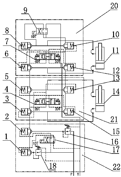
[0013] The technical solutions of the present invention will be further described below through specific embodiments in conjunction with the accompanying drawings.

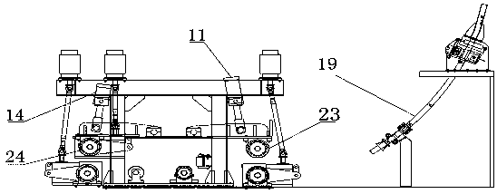
[0014] Such as figure 1 As shown, the present invention uses a plug-in logic valve to realize the hydraulic control method for tension leveling. The hydraulic control method for tension leveling of each stream of the continuous casting machine is the same, and they are all combined with functional integrated blocks using a cascading connection. Each stream has three functions. Manifolds, from bottom to top, are the decompression logic valve manifold 22, the billet drawing logic valve manifold 21, and the stripping logic valve manifold 20. The decompression logic valve manifold 22 is composed of a plug-in logic valve 1, a plug-in logic valve 2, a low-pressure pressure relief valve 16, a two-position four-way reversing valve 17, and a high-pressure pressure relief valve 18. The reversing valve 17 is a high-pressure...


PUM


Abstract

The invention relates to a method for achieving tension leveling hydraulic control through an inserting type logical valve, and belongs to the technical field of steel making continuous casting. According to the technical scheme, a tension leveling hydraulic control function unit is composed of stacking type logical valve integration blocks, and the tension leveling hydraulic control unit of one-piece flow of a continuous casting machine is composed of a pressure reducing unit, a blank pulling unit and a blank disengaging unit. Due to the fact that basic assemblies of a cartridge valve are standard parts and a valve element of the cartridge valve is of a conical valve element structure, the cartridge valve is high in reliability, in other words, the anti-clamping capability of the cartridge valve is greatly higher than that of an ordinary sliding valve, and the self dirt removing capability is achieved. Meanwhile, the circulation capability of the cartridge valve is much higher than that of the ordinary sliding valve, and due to the fact that assemblies of the cartridge valve are inserted in the hydraulic integration blocks, the structure of a hydraulic integration system composedof the cartridge valve is greatly reduced; and a basic unit is of a conical valve structure, inner leakage is extremely small, the response performance is good, and high-speed switchover can be conducted.

Description

technical field [0001] The invention relates to a method for realizing tension-leveling hydraulic control by using a plug-in logic valve, and belongs to the technical field of steelmaking and continuous casting. Background technique [0002] The continuous casting machine is an important smelting equipment in the steelmaking plant, and the tension leveling machine is the core process equipment in the continuous casting process. The molten steel is poured into the tundish through the ladle, and then diverted from the tundish to each crystallizer, and cast into a billet. The tension leveler pulls out billets with different specifications and cross-sections; the hydraulic control method of tension leveler is an important part of the tension leveler. At present, the hydraulic control of the stretching and leveling machine mainly adopts the continuous casting of integrated blocks and plate valves for control, so that the hydraulic control valve group of the stretching and levelin...

Claims


Application Information

Patent Timeline
Patent Type & Authority Patents(China)
IPC IPC(8): F15B13/08B22D11/12
Inventor 杨高瞻胡泽东贺玉军崔光宇赵贝贝肖博超李新民魏军刘振
Owner 河北张宣高科科技有限公司
Learn More