
Power semiconductor device and manufacturing method thereof

A technology of power semiconductor and manufacturing method, applied in the direction of semiconductor devices, electrical components, circuits, etc., can solve the problems of weakening the charge compensation effect of the device and the thickness of the field oxygen layer, so as to suppress the enhancement of the surface electric field, reduce the on-resistance, The effect of improving reliability

Pending Publication Date: 2018-01-19
WUXI NCE POWER
View PDF0 Cites 3 Cited by
  • Summary
  • Abstract
  • Description
  • Claims
  • Application Information

AI Technical Summary

Problems solved by technology

The thickness of the field oxygen layer at the bottom of the deep trench MOSFET is closely related to the withstand voltage of the device. The thicker the field oxide layer at the bottom of the trench, the higher the withstand voltage of the device. In the manufacturing process, due to process factors, the trench sidewall The thickness of the field oxygen layer is close to the thickness of the field oxygen layer at the bottom of the trench, resulting in the thickness of the field oxygen layer on the sidewall of the trench being too thick
The charge compensation effect between deep trench MOSFET trenches is related to the thickness of the field oxygen layer on the sidewall of the trench. An overly thick field oxygen layer on the sidewall of the trench will weaken the charge compensation effect of the device, so that when the device is subjected to withstand voltage , the electric field on the surface of the device is enhanced, which will lead to a decrease in the avalanche withstand capacity of the device
In order to reduce the surface electric field of the device, manufacturers usually increase the resistivity of the epitaxial layer between the trenches of deep trench MOSFETs, and this method will significantly increase the on-resistance of the device

Method used


Image

  • Power semiconductor device and manufacturing method thereof
  • Power semiconductor device and manufacturing method thereof
  • Power semiconductor device and manufacturing method thereof

Examples


Embodiment Construction

[0054] The specific embodiments of the present invention will be described in detail below with reference to the accompanying drawings. It should be understood that the specific embodiments described herein are only used to illustrate and explain the present invention, but not to limit the present invention.

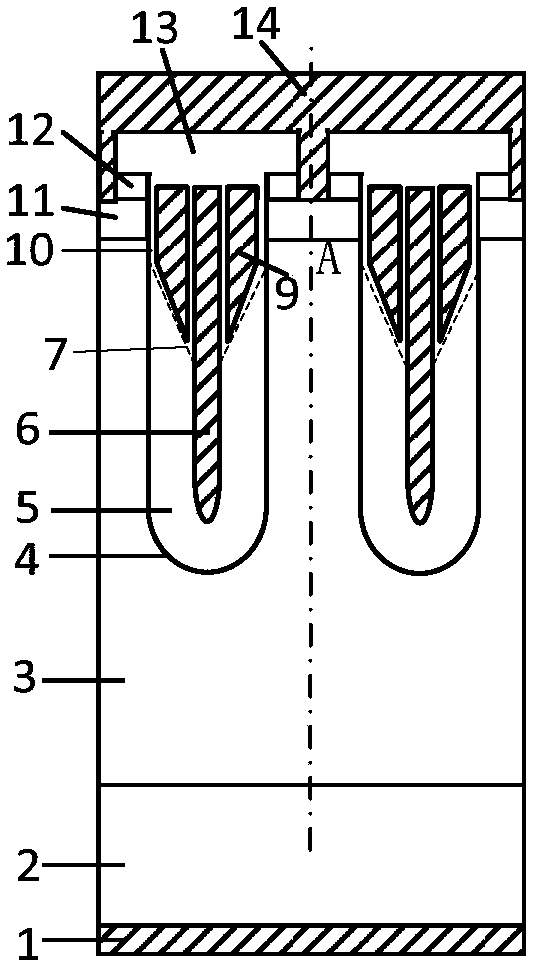
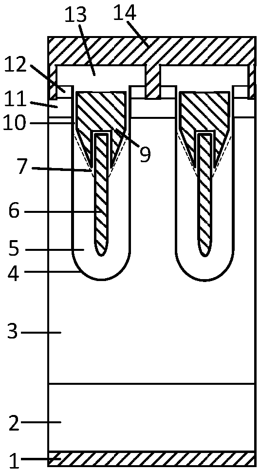
[0055] As a first aspect of the present invention, a power semiconductor device is provided, comprising a cell area and a terminal protection area, the cell area is located in the center of the power semiconductor device, and the terminal protection area surrounds the cell area settings, such as figure 2 As shown, the cell region includes a first-conductivity-type silicon substrate 2 and a first-conductivity-type epitaxial layer 3 disposed on the first-conductivity-type silicon substrate 2, on the first-conductivity-type epitaxial layer 3 The surface is provided with a second conductivity type body region 11 , and a U-shaped trench 4 is formed in the second conductivit...


PUM


Abstract

The invention discloses a power semiconductor device, which comprises a cell area, a terminal protection area, a first type of insulating dielectric body and a first type of electric conductor, wherein the cell area comprises a substrate of a first conductivity type and an epitaxial layer of a first conductivity type; a U-shaped groove is formed in the epitaxial layer of the first conductivity type; the groove is filled with the first type of insulating dielectric body and the first type of electric conductor; the first type of insulating dielectric body is arranged in a manner of surroundingthe first type of electric conductor; inner grooves are formed between one of two sides of the upper end of the first type of electric conductor and the first type of insulating dielectric body and between the other side and the epitaxial layer of the first conductivity type separately, and the cross section of each inner groove is in a right-angled trapezoid form; an acute angle in a right-angledtrapezoid form is formed between the first type of insulating dielectric body and the first type of electric conductor; and gate-conductive polysilicon matched with the inner grooves is arranged in the inner grooves. The invention further discloses a manufacturing method of the power semiconductor device. According to the power semiconductor device, the on-resistance of the device is obviously reduced.

Description

technical field [0001] The present invention relates to the technical field of semiconductor devices and their manufacturing, and in particular, to a power semiconductor device and a manufacturing method of the power semiconductor device. Background technique [0002] In the field of power semiconductor devices, deep trench MOSFETs can significantly improve the channel density and reduce the characteristic on-resistance. Therefore, deep trench MOSFETs have been widely used. The thickness of the field oxide layer at the bottom of the trench of a deep trench MOSFET is closely related to the withstand voltage of the device. The thicker the thickness of the field oxide layer at the bottom of the trench, the higher the withstand voltage of the device. The thickness of the field oxide layer is close to the thickness of the field oxide layer at the bottom of the trench, resulting in an excessively thick field oxide layer on the sidewall of the trench. The charge compensation eff...

Claims


Application Information

Patent Timeline
Patent Type & Authority Applications(China)
IPC IPC(8): H01L29/06H01L29/78
Inventor 朱袁正周锦程叶鹏刘晶晶
Owner WUXI NCE POWER
Learn More