An Optimal Design Method for Plate Structures to Improve Low-Frequency Sound Insulation Performance
A technology for optimizing design and flat plate, applied in geometric CAD and other directions
- Summary
- Abstract
- Description
- Claims
- Application Information
AI Technical Summary
Problems solved by technology
Method used
Image
Examples
Embodiment 1
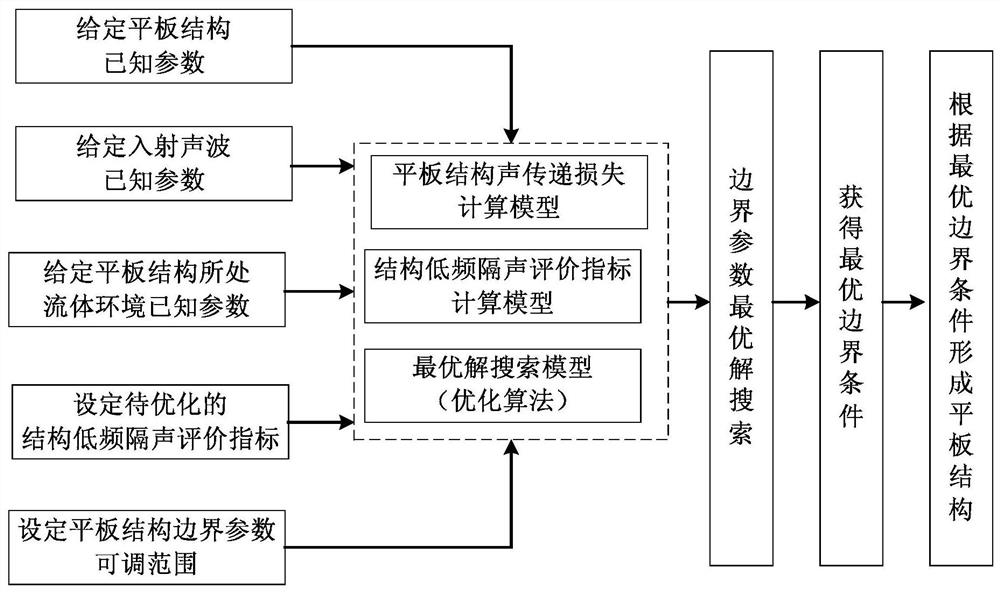
[0054] Embodiment 1, the specific optimization steps are as follows:
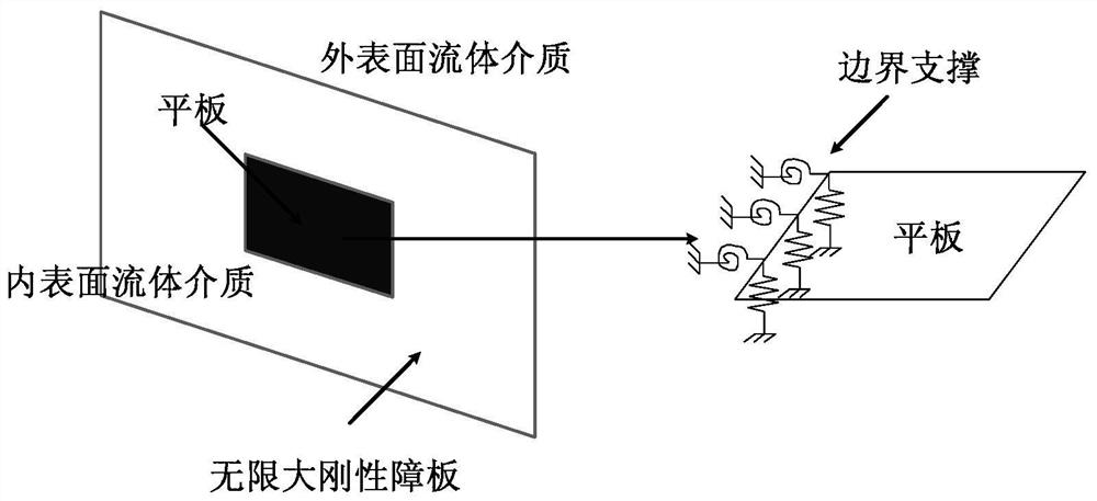
[0055] Step 1. Establish the calculation equation for the sound transmission loss of the plate structure applicable to any boundary conditions:
[0056]
[0057] Among them, TL is the sound transmission loss of the plate structure, {δ} is the node displacement vector matrix, and ω is the natural angular frequency. is the global transformation matrix, which can convert the unit load pressure into the equivalent nodal force; is the global transformation matrix, which can convert the nodal displacement into lateral deflection; {P 0} is the incident acoustic wave matrix acting on the inner surface of the plate, {M}, {C} and {K} are the overall mass matrix, damping matrix and overall stiffness matrix of the plate structure respectively, which can be obtained by the finite element method, as follows: {M } by the equivalent mass matrix of the plate element {M p} e Composed of, {K} consists of the equivalen...
Embodiment 2
[0112] Step 1. Establish the calculation equation of the sound transmission loss of the plate structure applicable to any boundary conditions;
[0113] Step 2. Set various known parameters, wherein the incident sound wave is a vertical incident sound wave (that is, the incident direction of the incident sound wave is consistent with the normal direction of the flat plate structure), and other specific parameter values are shown in Table 5 below:
[0114]
[0115] Table 5 known parameters
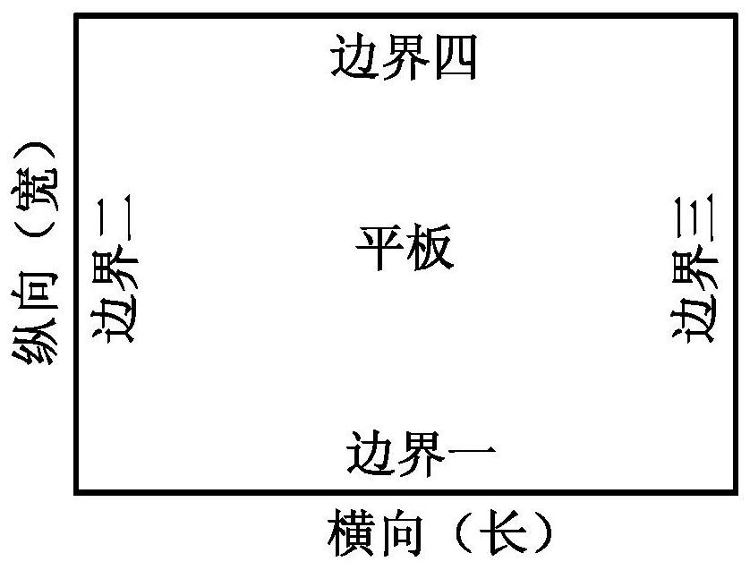
[0116] Step 3. Set the adjustable range of boundary parameters, as shown in the table below:
[0117]
[0118] Table 6 Boundary parameters
[0119] Step 4. Select LFSTC at the same time A and LFSTC O&N indicators, and establish calculation methods corresponding to these two indicators;
[0120] Step 5. According to the indicators selected in step 4, set the optimization goal of the flat plate structure as: simultaneously realize the selected LFSTC A and LFSTC O&N index value is...
PUM
 Abstract
Description
Claims
Application Information
 - R&D
- Intellectual Property
- Life Sciences
- Materials
- Tech Scout
- Unparalleled Data Quality
- Higher Quality Content
- 60% Fewer Hallucinations
Browse by: Latest US Patents, China's latest patents, Technical Efficacy Thesaurus, Application Domain, Technology Topic, Popular Technical Reports.
© 2025 PatSnap. All rights reserved.Legal|Privacy policy|Modern Slavery Act Transparency Statement|Sitemap|About US| Contact US: help@patsnap.com


