
Slab structure optimal design method for improving low-frequency sound insulation performance

An optimized design, flat-panel technology, applied in computing, special data processing applications, instruments, etc., to achieve the effect of improving sound insulation performance, reducing interference and harm, and improving insulation capacity

Active Publication Date: 2018-01-09
HUAQIAO UNIVERSITY
View PDF2 Cites 7 Cited by
  • Summary
  • Abstract
  • Description
  • Claims
  • Application Information

AI Technical Summary

Problems solved by technology

However, there is no optimal design method that can effectively guide the optimal design of the boundary conditions of the flat plate structure, so as to achieve the maximum improvement of the low-frequency sound insulation performance

Method used


Image

  • Slab structure optimal design method for improving low-frequency sound insulation performance
  • Slab structure optimal design method for improving low-frequency sound insulation performance
  • Slab structure optimal design method for improving low-frequency sound insulation performance

Examples


Embodiment 1

[0054] Embodiment 1, the specific optimization steps are as follows:

[0055] Step 1. Establish the calculation equation of plate structure-acoustic transmission loss applicable to any boundary conditions:

[0056]

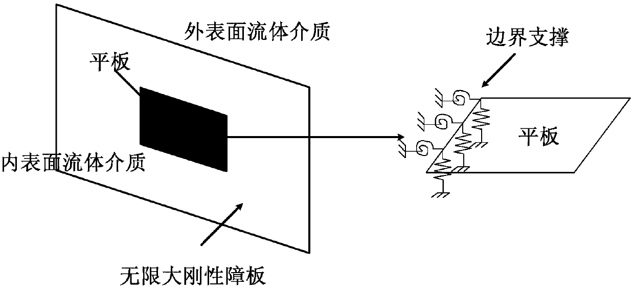
[0057] Among them, TL is the sound transmission loss of the plate structure, {δ} is the node displacement vector, and ω is the natural angular frequency. is the global transformation matrix, which can convert the unit load pressure into the equivalent nodal force; is the global transformation matrix, which can convert the nodal displacement into lateral deflection; {P 0} is the incident sound wave acting on the inner surface of the plate, {M}, {C} and {K} are the overall mass matrix, damping matrix and overall stiffness matrix of the plate structure respectively, which can be obtained by the finite element method, as follows: {M} Equivalent mass matrix {M p} e Composed of, {K} consists of the equivalent stiffness matrix of the plate element {K p} e and ...

Embodiment 2

[0111] Step 1. Establish the calculation equation of the plate structure-acoustic transmission loss applicable to any boundary conditions;

[0112] Step 2. Set various known parameters, where the incident sound wave is a vertical incident sound wave (that is, the incident direction of the incident sound wave is consistent with the normal direction of the flat plate structure), and other specific parameter values ​​are shown in Table 5 below:

[0113]

[0114] Table 5 known parameters

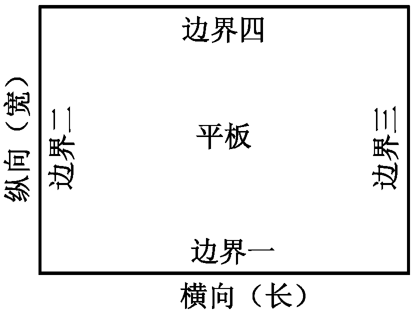
[0115] Step 3. Set the adjustable range of boundary parameters, as shown in the table below:

[0116]

[0117] Table 6 Boundary parameters

[0118] Step 4. Select LFSTC at the same time A and LFSTC O&N indicators, and establish calculation methods corresponding to these two indicators;

[0119] Step 5. According to the indicators selected in step 4, set the optimization goal of the flat plate structure as follows: Simultaneously realize the selected LFSTC A and LFSTC O&N index value ...


PUM


Abstract

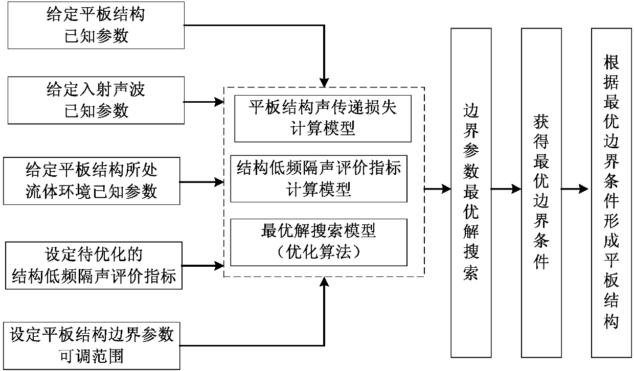
The invention discloses a slab structure optimal design method for improving low-frequency sound insulation performance. The method comprises the steps that a calculation equation suitable for sound transmission loss of a slab structure under arbitrary boundary conditions is established, and all known parameters are set; one or more structure low-frequency sound insulation performance evaluation indexes are selected; a calculation method corresponding to the selected indexes is established; an optimization objective of the slab structure is set according to the selected indexes; if the numberof the selected indexes in the step 4 is more than 1, corresponding weights of all the indexes are set; an optimization algorithm is selected; and optimal solution search is performed according to theset known parameters, a boundary parameter adjustable range and the optimization objective to obtain optimal boundary parameters and form the slab structure. The method can guide optimal design of the boundary conditions of the slab structure, the advantages of the optimization algorithm are utilized in the design process, an optimal solution to the boundary conditions is quickly searched out, and therefore the effect of maximizing the low-frequency sound insulation performance of the slab structure is achieved.

Description

technical field [0001] The invention relates to an optimal design method of a flat panel structure for improving low-frequency sound insulation performance. Background technique [0002] The sound insulation and noise reduction characteristics of structures have always been a concern in the fields of architecture and machinery. In order to effectively evaluate the sound insulation performance of structures, the "single value evaluation" index of structural sound insulation performance has been proposed. For example, the sound transmission class "Sound Transmission Class" (STC) proposed by the ASTM organization, the weighted sound attenuation index "Weighted Sound Reduction Index" (Rw) proposed by the ISO International Organization for Standardization, and the sound insulation evaluation standard proposed in my country "Single Value Evaluation Quantity", etc. However, the above single-valued evaluation index does not consider the low-frequency range enough, and it is difficu...

Claims


Application Information

Patent Timeline
Patent Type & Authority Applications(China)
IPC IPC(8): G06F17/50
Inventor 欧达毅
Owner HUAQIAO UNIVERSITY
Learn More