
Fluid extracting-discharging apparatus and immersion type photoetching machine

A technology of fluid and flow guide mechanism, applied in the field of photolithography, can solve problems such as unstable immersion flow field pressure, unstable pipeline pressure, and affecting exposure quality, and achieve the effect of simple structure, stable pressure, and improved exposure quality

Active Publication Date: 2018-01-09
SHANGHAI MICRO ELECTRONICS EQUIP (GRP) CO LTD
View PDF10 Cites 2 Cited by
  • Summary
  • Abstract
  • Description
  • Claims
  • Application Information

AI Technical Summary

Problems solved by technology

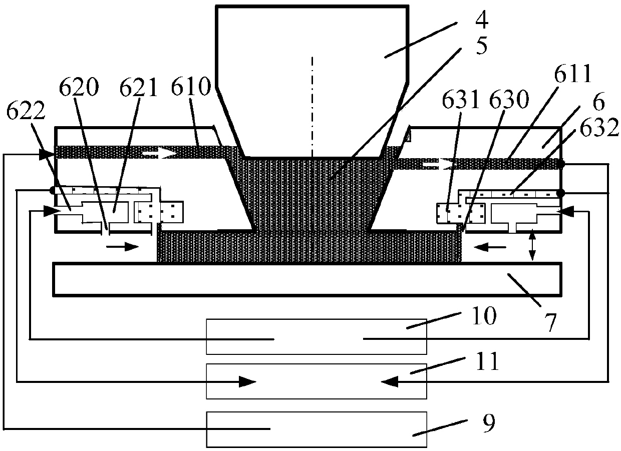
[0008] The invention provides a fluid pumping device, which is used to solve the problem that the gas-liquid two-phase flow of the traditional immersion photolithography machine is easy to form a "water plug" in the pumping line and collapse quickly, making the pressure in the line unstable. , which in turn affects the pressure instability in the immersion liquid flow field and affects the exposure quality

Method used


Image

  • Fluid extracting-discharging apparatus and immersion type photoetching machine
  • Fluid extracting-discharging apparatus and immersion type photoetching machine
  • Fluid extracting-discharging apparatus and immersion type photoetching machine

Examples


Embodiment 1

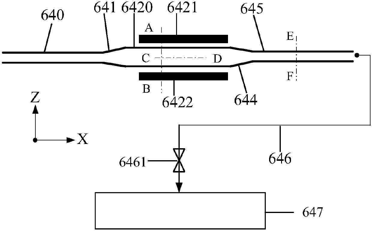
[0046] see image 3 with Figure 4 , a fluid pumping device, connected to the immersion head 6 and the gas-liquid recovery device 647 for pumping the gas-liquid two-phase flow at the edge of the immersion liquid flow field in the immersion head 6 to the gas-liquid recovery device 647, the The fluid pumping device includes a first pumping tube 640, a first flow guide mechanism 641, an atomization chamber, a second flow guide mechanism 644, a second pumping tube 645, and a third pumping tube 646 connected in sequence. A suction pipe 640 is connected to the immersion head 6, and the gas-liquid two-phase flow at the edge of the immersion liquid flow field is pumped out of the immersion head 6 through the gas-liquid suction pipe and enters the first suction pipe 640 , thereby entering the fluid pumping device.

[0047] see Figure 5 with Image 6 , image 3 The cross-sectional structures at positions A-B and C-D, the atomization chamber includes a chamber 6420 with left and ri...

Embodiment 2

[0053] see Figure 8 The difference between embodiment 2 and embodiment 1 is that two sets of first flow guide rib arrays 6423 are arranged in the atomization chamber, and the first flow guide rib arrays 6423 divide the gas-liquid two-phase flow and separate For isotropic processing, there is a certain gap between the two groups of the first diversion rib arrays 6423, and they are not connected to each other as a whole. There are gaps between the third guide rib arrays 6442, and they are not connected to each other as a whole.

[0054] The fluid pumping device also includes a surfactant injection device and an air supply device. The surfactant injection device includes a surfactant supply pipeline 6481, a surfactant injection device 6482 and a surfactant flow control valve 6483. One end of the surfactant supply pipeline 6481 is connected to the surfactant injection device 6482, and the other end is connected to the atomization chamber, and the mouth of the surfactant supply p...


PUM

PropertyMeasurementUnit
lengthaaaaaaaaaa

Abstract

The invention discloses a fluid extracting-discharging apparatus used for extracting and discharging a gas-liquid mixture from the edge of an immersion liquid flow field in an immersion head to gas-liquid recycling equipment; the fluid extracting-discharging apparatus comprises a first extracting-discharging pipe, an atomizing cavity and a second extracting-discharging pipe connected in sequence;the gas-liquid mixture enters the atomizing cavity to be atomized through the first extracting-discharging pipe; then the atomized mixture enters the gas-liquid recycling equipment through the secondextracting-discharging pipe; by virtue of the fluid extracting-discharging apparatus, the anisotropic gas-liquid two-phase flow which flows to the fluid extracting-discharging apparatus can be converted into isotropous ''atomized-shaped'' single-phase flow, so that pressure balance in each position of the fluid extracting-discharging apparatus can be maintained; the invention also discloses an immersion type photoetching machine provided with the fluid extracting-discharging apparatus; and the immersion type photoetching machine is stable in the immersion liquid flow field, good in flow fieldsealing effect, and capable of effectively preventing a gas-liquid two-phase ''water plugging'' phenomenon generated in the pipeline by the gas-liquid mixture in the extracting and discharging position of the immersion liquid flow field, and improving exposure quality.

Description

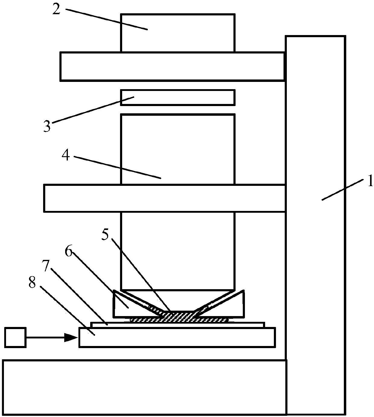
technical field [0001] The invention relates to the field of photolithography, in particular to a fluid pumping device and an immersion photolithography machine. Background technique [0002] Modern lithography equipment is based on optical lithography, which uses an optical system to accurately project and expose the pattern on the mask onto a substrate (such as a silicon wafer) coated with photoresist. Immersion lithography refers to the filling of water (or higher refractive index immersion liquid) between the exposure lens and the silicon wafer to form an immersion liquid flow field to replace the corresponding air in traditional dry lithography technology, due to the refractive index of water It is larger than air, which increases the numerical aperture of the lens group, thereby obtaining a smaller characteristic line width. [0003] See figure 1 , an immersion photolithography machine, including a main frame 1, an illumination system 2 arranged on the main frame 1, ...

Claims


Application Information

Patent Timeline
Patent Type & Authority Applications(China)
IPC IPC(8): G03F7/20
Inventor 赵丹平聂宏飞
Owner SHANGHAI MICRO ELECTRONICS EQUIP (GRP) CO LTD
Learn More