Embedded Microstrip Resonator, Wide Rejection Filter and Design Method

A resonator and filter technology, applied in resonators, waveguide-type devices, circuits, etc., can solve the problems of insufficient suppression, increase design complexity, and attenuation of useful signals, and achieve good suppression depth, superior effect, and structure. compact effect

Active Publication Date: 2019-09-20
TSINGHUA UNIV
View PDF5 Cites 0 Cited by
  • Summary
  • Abstract
  • Description
  • Claims
  • Application Information

AI Technical Summary

Problems solved by technology

[0004] In the literature [1], a band-stop filter is inserted into the band-pass filter to achieve wide stop-band suppression. This cascading method will increase the size of the device, which is not conducive to the miniaturization target requirements; in addition, The increase in the number of filters in the system will also increase the insertion loss of the filter, attenuate the passing useful signal, and affect the overall performance of the receiver, which is not conducive to the high-performance target requirements
[0005] In literature [2], an asymmetrical step impedance resonator is used to realize a wide rejection filter by means of interleaved frequency doubling. This method adjusts the resonant peaks of each resonator to make the multiplied frequency evenly distributed, thereby achieving a wide stopband The effect, the suppression degree can reach more than 20dB, but this method only makes the spurious resonant resonant frequencies interleave with each other, and fails to move or directly eliminate the resonance peak, so the suppression degree is usually not high enough. In addition, each resonator needs to be designed and adjusted , increasing the complexity of the design

Method used


Image

  • Embedded Microstrip Resonator, Wide Rejection Filter and Design Method
  • Embedded Microstrip Resonator, Wide Rejection Filter and Design Method
  • Embedded Microstrip Resonator, Wide Rejection Filter and Design Method

Examples


Embodiment 1

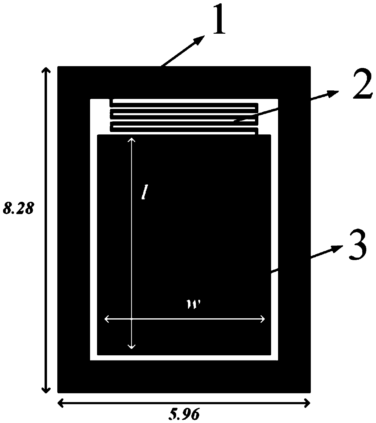
[0060] According to the requirements of the center frequency of the filter at 849.3MHz, refer to figure 2 , 3 , 4, 5, designed Figure 8 The resonator, the resonant frequency of the resonator is 849.3MHz, the first spurious frequency f s with fundamental frequency f 0 The ratio f s / f 0 is 4.6.

[0061] According to the requirement of 3dB bandwidth of 13.86MHz, in a four-section filter, the coupling coefficient of the first and second section resonators is determined to be 0.01764, the coupling coefficient of the second and third section resonators is 0.01296, and the coupling coefficient of the third and fourth section resonators The coupling coefficient is 0.01764 and the external Q value is 43.68.

[0062] According to the above coupling coefficient, adjust the distance between each resonator, design the following Figure 9 As shown in the wide-suppression superconducting filter pattern, the first and last two sections are feeders with a width of 0.48mm, and the ove...


PUM


Abstract

The invention discloses an embedded type microstrip resonator. The embedded type microstrip resonator comprises a first low impedance block, a high impedance block and a second low impedance block; the first low impedance block adopts a blocky structure and the interior thereof is subjected to hollow-out treatment; the second low impedance block adopts a blocky structure, and the high impedance block adopts a zigzagging line structure; the second low impedance block and the high impedance block are positioned in the first low impedance block; and high impedance block is connected with the two low impedance blocks. By adjusting the sum of the lengths of the three impedance blocks, the central frequency of the resonator is adjusted; by adjusting the length l and / or the width w of the second low impedance block, the ratio of first parasitic frequency f<s> to fundamental frequency f<0> of the resonator is adjusted; and by changing the distance between adjacent embedded type microstrip resonators, the coupling coefficient of each section of filtering can be changed. The invention also provides a high-suppression filter formed by adopting the embedded type microstrip resonator, and a design method therefor; and the high-performance and small-sized filter can be designed.

Description

technical field [0001] The invention belongs to the technical field of microwave engineering, and in particular relates to an embedded microstrip resonator, a wide suppression filter designed by using the embedded microstrip resonator, and a design method of the wide suppression filter. Background technique [0002] With the rapid development of wireless communication technology, as more and more communication frequency band resources are developed and utilized, and more and more communication devices are put into use, the space electromagnetic field environment has become more complex than before, and the problem of radio frequency interference is becoming more and more serious. The demand for high-performance microwave receiver front-end is increasingly urgent. As one of the core components of the microwave receiver front-end, the filter plays the role of frequency selection and anti-interference. Miniaturized and high-performance filters have always been the target require...

Claims


Application Information

Patent Timeline
Patent Type & Authority Patents(China)
IPC IPC(8): H01P7/08H01P1/203H01P11/00
Inventor 魏斌曹必松郭旭波王翔王丹
Owner TSINGHUA UNIV
Why Eureka
Try Eureka