Cold storage device, in particular for an automobile

a storage device and automobile technology, applied in the direction of indirect heat exchangers, domestic cooling devices, lighting and heating devices, etc., can solve the problems of accumulator damage or possibly destruction, heightened risk of damage, and air conditioning of automobiles still lacking a certain level of comfor

Inactive Publication Date: 2000-08-15
BEHR GMBH & CO KG
View PDF21 Cites 39 Cited by
  • Summary
  • Abstract
  • Description
  • Claims
  • Application Information

AI Technical Summary

Benefits of technology

The result is a cold storage device that may have a small structural volume, because the storage medium carrier itself is able to accommodate volume changes. Furthermore, the cold storage device according to the invention can be produced very cost-effectively. The storage medium is absorbed by the storage medium carrier and, therefore, the storage medium is prevented from "sloshing about" in the housing of the cold storage device and an associated "sloshing noise," which is found to be intrusive, is avoided.
A further advantage is that the cold storage device according to the invention can be designed in the manner of known heat exchangers that have proven successful in use. The material of the storage medium carrier simply can be added in later, for example between tubes of the heat exchanger. Thus, it is possible to use known, tried-and-tested, optimized processes for producing heat exchangers and known heat exchanger designs. It is possible, for example, to use round tube or flat tube heat exchanger designs, which have been utilized in automotive construction for long periods of time.
The storage medium is preferably water, and the storage medium carrier preferably comprises a woven fabric, a knitted fabric or a non-woven. Such structures, in particular non-wovens, have long been used, for example in sanitary products, such as disposal diapers or incontinence products. They are extremely inexpensive and have a high liquid absorption capacity, allowing these substances to compensate for changes in storage medium volume to a sufficient extent even when they are loaded with storage medium to the maximum extent.
If the storage medium carrier is designed as a powder or a pourable substance, there are advantages for the manufacturing process, because, first of all, the heat exchanger structure, i.e., the tubes and ribs, can be manufactured in a known, tried-and-tested way, and then the heat exchanger structure can be filled with the storage medium carrier. As a result, producing the accumulator according to the invention does not require a completely new manufacturing process, but rather merely entails an additional manufacturing step.
Ribs, or fins, comprising a good thermally conductive material are provided to improve the thermal conductivity. The ribs may be constructed, for example, of aluminum.
Preferably, the ribs or fins and the storage medium carrier form a layered structure that is connected to the pipes. This ensures optimum heat transfer between the storage medium contained in the storage medium carrier and the heat transfer medium flowing inside the pipes.

Problems solved by technology

Despite high-performance air-conditioning systems, the air conditioning of automobiles still lacks a certain level of comfort, because at high external temperatures and / or in strong sunshine the vehicle interior is often at a high temperature when the occupant first enters the vehicle.
There are essentially three core problems that have to be solved when designing cold storage devices.
More particularly, the change in volume caused by phase change is of central importance, because a volume expansion can quickly cause the accumulator to be damaged or possibly destroyed.
For example, water expands when it is frozen, therefore , when it is used as the storage medium there is a heightened risk of damage due to water's changing volume.
Such designs cannot be employed in automotive engineering, because of a lack of sufficient space in vehicles and the associated demand for compact designs, and because of the extreme climatic conditions to which a vehicle may be exposed and which the accumulator has to withstand.

Method used


Image

  • Cold storage device, in particular for an automobile
  • Cold storage device, in particular for an automobile
  • Cold storage device, in particular for an automobile

Examples


Embodiment Construction

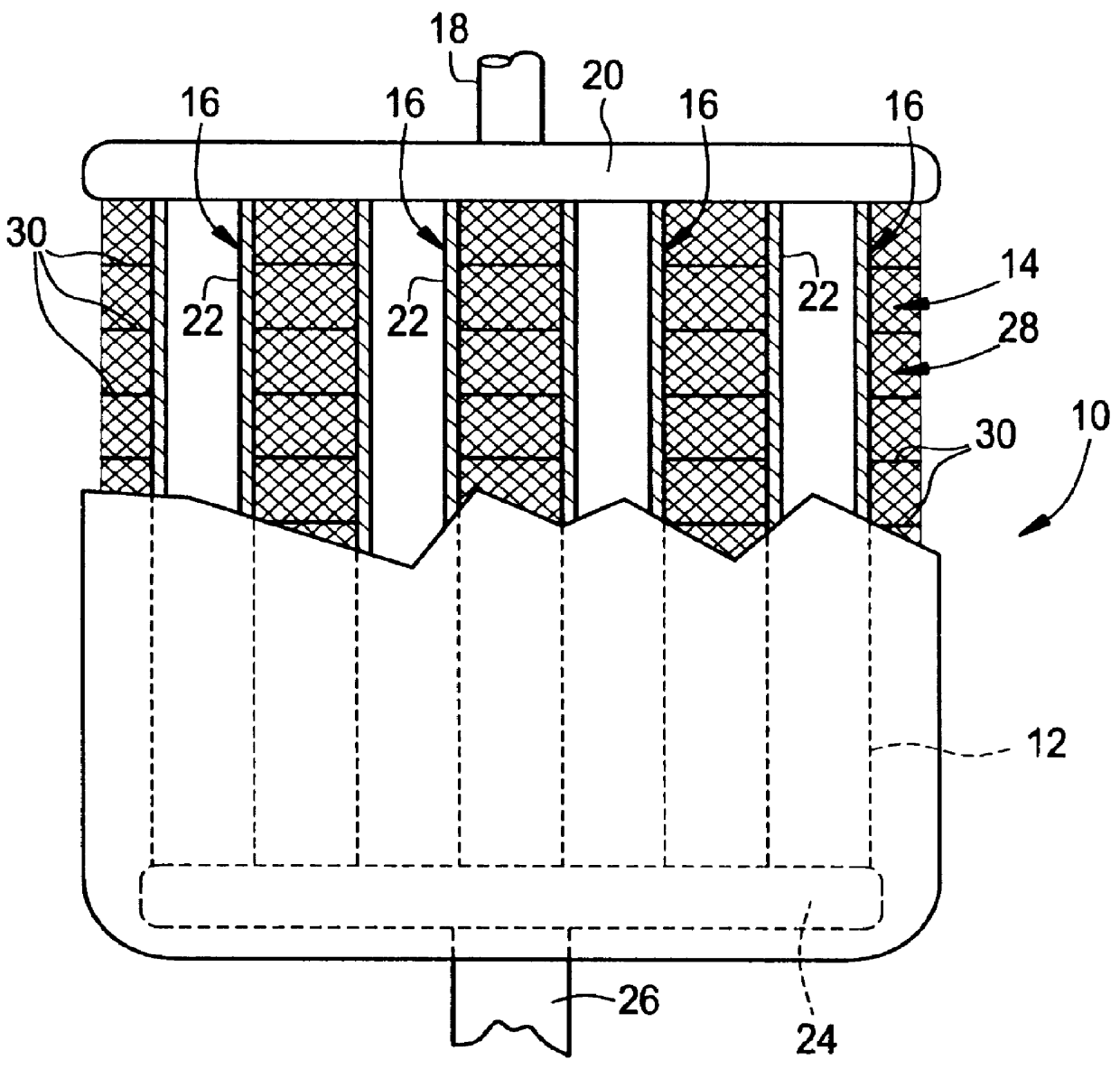
According to the invention, the storage medium is held by a storage medium carrier comprising an absorbent material. Furthermore, the storage medium, in its liquid state, is completely absorbed by the storage medium carrier. The absorbent material makes it possible to compensate sufficiently for changes in volume without damaging the cold storage device. The absorbent material may be any of a wide variety of substances that absorb the storage medium, for example, an absorbent material that is capable of taking up between about 30% by volume and about 90% by volume of the storage medium. The absorbent material may employ any means or any desired type of interaction, for example, hydrophilic, capillary or colloidal. A residual volume of the absorbent material, which is able to compensate for the changes in volume of the absorbed storage medium, always remains.

The result is a cold storage device that may have a small structural volume, because the storage medium carrier itself is able ...


PUM


Abstract

The invention relates to a cold storage device, in particular for an automobile, having a storage medium for storing cold and a storage medium carrier that is connected in a thermally conductive manner to pipes for carrying a heat transfer medium for charging or discharging the cold storage device. To provide an improved cold storage device particularly suitable for use in an automobile, that is able to accommodate changes in volume of the storage medium while itself having a small structural volume and which can be produced cost-effectively, the storage medium carrier comprises an absorbent material, and the storage medium, in its liquid state, is preferably completely absorbed by the storage medium carrier.

Description

1. Field of the InventionThe invention relates to a cold storage device, particularly, for use with an automobile air conditioning system, whereby the temperature of a vehicle interior can be cooled more quickly.2. Description of Related ArtDespite high-performance air-conditioning systems, the air conditioning of automobiles still lacks a certain level of comfort, because at high external temperatures and / or in strong sunshine the vehicle interior is often at a high temperature when the occupant first enters the vehicle. Therefore, a certain period of time is required after starting the vehicle before a pleasant temperature is reached in the vehicle interior. In order to reduce this cooling time and to cool the vehicle interior more quickly, cold storage devices, which are able to release very high cooling capacities within a short time, are utilized.There are essentially three core problems that have to be solved when designing cold storage devices. It is necessary to provide a go...

Claims


Application Information

Patent Timeline
IPC IPC(8): B60H1/00F25D3/00F28D20/02B60H1/32F25D3/02
CPCB60H1/005F25D3/005F28D20/02F28D20/023Y02E60/145Y02E60/14
Inventor FEUERECKER, GUNTHER
Owner BEHR GMBH & CO KG
Why Eureka
Try Eureka