
Additive manufacturing method for metal part

A technology for metal parts and additive manufacturing, which is applied in the field of composite additive manufacturing of metal parts using arc deposition-laser surface melting, which can solve the problem of poor surface flatness of parts, dimensional accuracy inferior to laser and electron beam additive manufacturing, and surface flatness. Improve the performance, improve the flatness and quality of surface forming, and improve the surface hardness

Inactive Publication Date: 2017-12-15
北京煜鼎增材制造研究院股份有限公司
View PDF8 Cites 36 Cited by
  • Summary
  • Abstract
  • Description
  • Claims
  • Application Information

AI Technical Summary

Problems solved by technology

Therefore, the use of arc additive manufacturing technology can achieve high melting deposition efficiency and low-cost additive manufacturing of complex and large metal parts; however, the dimensional accuracy of arc additive manufacturing parts is not as good as laser and electron beam additive manufacturing, especially in high melting deposition efficiency. Under the process conditions, the surface flatness of arc additive manufacturing parts is poor, and the surface flatness decreases with the increase of metal melting deposition efficiency

Method used


Image

  • Additive manufacturing method for metal part
  • Additive manufacturing method for metal part
  • Additive manufacturing method for metal part

Examples


Embodiment 1

[0039] (1) Design the CAD model of the part, and process the model in layers, and then plan the melting deposition path for the specific shape characteristics of each layer after layering;

[0040] (2) The welding wire adopts 316L stainless steel welding wire with a diameter of 1.2mm;

[0041](3) Use a melting electrode arc power supply with a maximum current of 500A for arc additive manufacturing, and place the arc welding torch and substrate in a pure Ar gas-tight box, so that the entire fusion deposition forming process is carried out under the protection of an inert gas (oxygen content ≤ 80ppm), the arc welding torch is melted and deposited according to the planned path, and the side surface of the melted deposition layer is melted by laser at the same time as each layer is melted and deposited. Among them, the arc additive manufacturing parameters are as follows: arc current 300A, arc voltage 28V, arc The scanning speed is 600mm / min, the wire feeding speed is 10m / min, the...

Embodiment 2

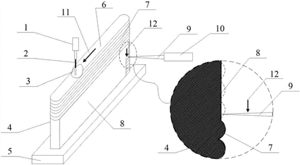
[0043] The difference from Example 1 is that after 10 layers are deposited by arc melting, laser surface melting treatment is carried out on the measured surface, wherein the laser melting parameters are as follows: laser power is 3.5kW, laser scanning speed is 1.5m / min, and the spot is 6mm directly. Road overlap 20%, the schematic diagram of additive manufacturing is as follows figure 2 shown.

Embodiment 3

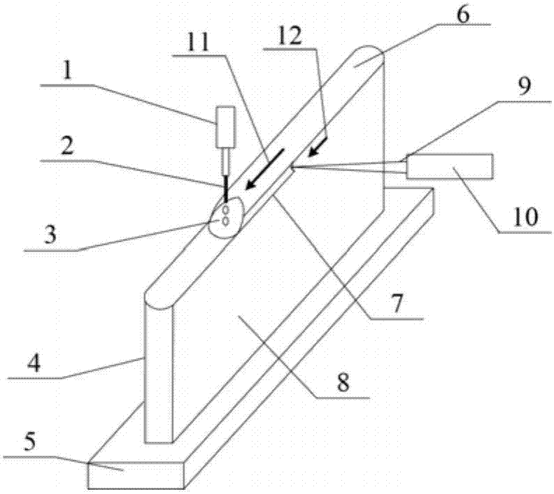
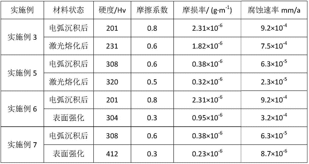
[0045] The difference from Embodiment 1 is that after the entire metal part is deposited by arc melting, laser surface melting is performed on the side surface of the part.


PUM

PropertyMeasurementUnit
thicknessaaaaaaaaaa
diameteraaaaaaaaaa
thicknessaaaaaaaaaa

Abstract

The invention discloses an additive manufacturing method for a metal part. The additive manufacturing method comprises the following steps of: (1) designing a CAD model according to the outline dimension of a metal part, performing layering processing on the model, and performing melting deposition path planning according to the specific appearance features of each layer subjected to layering processing; (2) preparing a material which is the same with the part in components into powder or a welding wire; (3) performing melting deposition on powder or the welding wire according to the planned path on a base plate through an electric-arc heat source; and (4) lifting a processing head by height of a deposition layer after melting deposition, repeating the step (3) to perform layer-by-layer melting deposition until a needed shape dimension of the metal part is reached. The method further comprises a step of performing laser melting on the surface of the melting deposition layer by laser or performing laser melting to generate a composite reinforcing layer. The additive manufacturing method disclosed by the invention effectively improves surface forming flatness and quality of the metal part, and reduces follow-up processing time and cost; and meanwhile, surface hardness, wear resistance and corrosion resistance of the metal part are also remarkably improved.

Description

technical field [0001] The invention relates to a method for additive manufacturing of metal parts, in particular to a method for manufacturing metal parts by using arc deposition-laser surface melting composite additive manufacturing. Background technique [0002] The additive manufacturing technology of metal parts was developed on the basis of Rapid Prototyping (RP) in the late 1990s, and it is an advanced manufacturing technology for directly preparing fully dense metal parts. It combines rapid prototyping manufacturing technology, high-power heat source (laser, electron beam, arc) melting deposition technology and advanced material preparation technology, adopts the idea of ​​digital discrete / stack forming additive manufacturing, and melts and deposits synchronously transported metal through high-power heat source Powder or wire is deposited layer by layer on the deposition substrate to achieve "near-net-shape manufacturing" of high-performance fully dense metal parts w...

Claims


Application Information

Patent Timeline
Patent Type & Authority Applications(China)
IPC IPC(8): B22F3/105B22F3/24B33Y10/00B23K9/04
CPCB22F3/1035B22F3/24B23K9/04B33Y10/00B22F10/00B22F10/25B22F12/41B22F10/32B22F10/50Y02P10/25
Inventor 张凌云陈晓晖
Owner 北京煜鼎增材制造研究院股份有限公司
Learn More