
Virtual synchronous generator control method based on self-adapting moment inertia

A technology of generator control and rotational inertia, applied in electrical components, circuit devices, AC network circuits, etc., can solve the problems of long transient process and poor power quality, and achieve the goal of improving stability, adaptability and power quality. Effect

Inactive Publication Date: 2017-12-12
SHANGHAI UNIVERSITY OF ELECTRIC POWER
View PDF4 Cites 58 Cited by
  • Summary
  • Abstract
  • Description
  • Claims
  • Application Information

AI Technical Summary

Problems solved by technology

[0005] Aiming at the problems of long transient process and poor power quality in virtual synchronous generators, the present invention proposes a virtual synchronous generator control method based on adaptive rotational inertia. After analyzing the structure principle of VSG, it proposes a A New Adaptive Rotational Inertia Scheme

Method used


Image

  • Virtual synchronous generator control method based on self-adapting moment inertia
  • Virtual synchronous generator control method based on self-adapting moment inertia
  • Virtual synchronous generator control method based on self-adapting moment inertia

Examples


Embodiment Construction

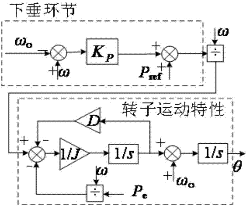
[0026] In order to make the DG system have the characteristics of synchronous generators, avoid introducing too many transient variables of synchronous generators, and avoid complex electromagnetic coupling relationships, the present invention adopts the classical second-order model of synchronous generators to establish a mathematical model. Its expression is:

[0027]

[0028] In the formula: J is the moment of inertia of the synchronous motor; T m , T e are the mechanical torque and electromagnetic torque of the synchronous generator; D is the damping coefficient; ω o is the grid synchronous angular velocity; P m ,P e are the mechanical power and electromagnetic power of the synchronous generator, respectively.

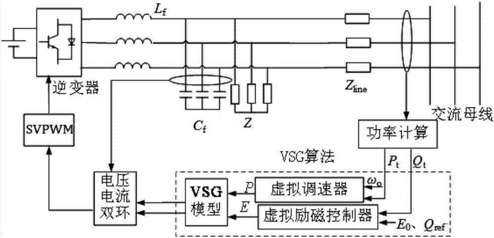
[0029] figure 1 It is a block diagram of the inverter control system based on VSG. The output of the micro-power grid-connected inverter of distributed generation passes through the filter inductor L f in parallel with the filter capacitor C f Connect to...


PUM


Abstract

The invention relates to a virtual synchronous generator control method based on self-adapting moment inertia. The output of a grid-connected inverter in distributed generation is connected with an AC bus of a filter capacitor Cf which is in parallel connection with the grid-connected inverter through a filter inductor Lf; sampling is performed to obtain the output power, the voltage and the current of an output interface of an inverter; the output power, the voltage and the current are transmitted to a VSG (virtual synchronous generator) algorithm; the calculated terminal voltage of a VSG stator is sent to be controlled by a voltage external loop; the voltage external loop adopts a PI controller to stably load the voltage; the current of the filter capacitor is sent to be controlled by a voltage internal loop; the voltage internal loop adopts a PI controller to increase the response speed; a control signal is outputted by a voltage-current dual-closed loop to the grid-connected inverter; the moment inertia in the virtual synchronous generator in the control method can be changed in a self-adapted manner according to the change capacity of the system frequency. Through the adoption of the virtual synchronous generator control method disclosed by the invention, the transient state process of the system is reduced; a great deal of harmonic waves in the system is offset; the stability of frequency and the stability of voltage can be improved; the adaptability and the power supply quality of a micro-electrical network are improved; the problem that in a conventional method, the output frequency is reduced, is solved.

Description

technical field [0001] The invention relates to a virtual synchronous generator control technology, in particular to a virtual synchronous generator control method based on adaptive rotational inertia. Background technique [0002] With the aggravation of energy and environmental problems, distributed generation (Distributed generation, DG) and microgrid (microgrid) technologies have received extensive attention. Distributed power generation mainly uses power electronic inverters, which have great external differences compared with large power grid synchronous generators, such as smaller capacity, lower output impedance, and lack of system inertia. It is impossible to provide a certain quality of voltage and frequency support for active distribution networks containing micro-sources. [0003] Droop control is the most commonly used distributed generation control method in microgrids. It adjusts the output voltage and frequency of the droop controller by the inverter by tra...

Claims


Application Information

Patent Timeline
IPC IPC(8): H02J3/01H02J3/18
CPCH02J3/01H02J3/1842Y02E40/30Y02E40/40
Inventor 程启明褚思远谭冯忍张宇高杰余德清陈路李涛孙伟莎程尹曼
Owner SHANGHAI UNIVERSITY OF ELECTRIC POWER
Learn More