
Method for continuously monitoring corrosivity of field environment by utilizing corrosion sensor

A corrosion sensor and corrosive technology, which is applied in weather resistance/light resistance/corrosion resistance, instruments, measuring devices, etc., can solve problems that affect test results, short circuits, and data that cannot be scientifically and effectively analyzed, so as to promote sharing and long-term accumulation. Long service life, true representation of the effect of environmental corrosiveness

Active Publication Date: 2017-12-08
浙江钱浪智能信息科技有限公司
View PDF9 Cites 15 Cited by
  • Summary
  • Abstract
  • Description
  • Claims
  • Application Information

AI Technical Summary

Problems solved by technology

Due to the limitation of the design principle of the existing technology, there are two difficulties that cannot be overcome: one is that the service life of the corrosion sensor is short. The accumulation of products on the surface of the corrosion sensor can easily lead to a short circuit and affect the test results. At present, the service life of corrosion sensors manufactured based on the principle of galvanic corrosion generally does not exceed one year; second, the monitored data cannot be scientifically and effectively analyzed. Strictly speaking, the obtained current value is the galvanic current between dissimilar metals. The change of this current value can only represent the change of environmental corrosion, and cannot quantitatively evaluate the environmental corrosion.
Invention patent CN 104749094A discloses a manufacturing method of an atmospheric corrosion monitoring sensor. This patent uses two different types of metal wires or wires to be wound side by side on a cylindrical body with an insulating surface, which increases the service life of the corrosion sensor to more than 5 years. However, the design principle of the corrosion sensor in this patent is still based on the principle of galvanic corrosion, so there is still a problem that the monitored data cannot be scientifically and effectively analyzed, so the environmental corrosion cannot be quantitatively evaluated.

Method used


Image

  • Method for continuously monitoring corrosivity of field environment by utilizing corrosion sensor
  • Method for continuously monitoring corrosivity of field environment by utilizing corrosion sensor

Examples


Embodiment 1

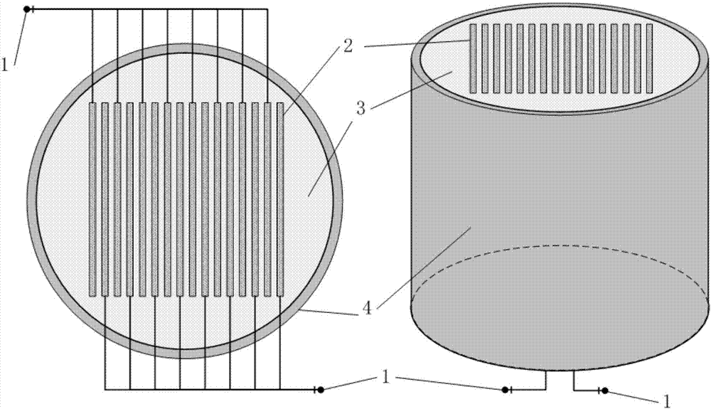
[0034] Select Q235 carbon steel material, prepare 16 pieces of metal test pieces with a size of 50mm×20mm×1mm by wire cutting method, use sandpaper to polish all the test pieces and degrease with acetone, weld copper wires on the width side of the test pieces and Divide into two groups and connect them in parallel to form two groups of electrode pairs. The carbon steel test pieces in the electrode pairs are arranged alternately in a cylindrical casing made of polytetrafluoroethylene, and sealed with epoxy resin. The epoxy resin is completely sealed. After curing, the electrode exposed at one end of the casing is polished and degreased again, and the corrosion sensor of the present invention is manufactured.

[0035] The corrosion sensor manufactured by the present invention is placed in the NaCl solution of 3.5% by weight, and the two wires of the corrosion sensor are respectively connected to the working electrode and the auxiliary electrode of the commercially available PS268...

Embodiment 2

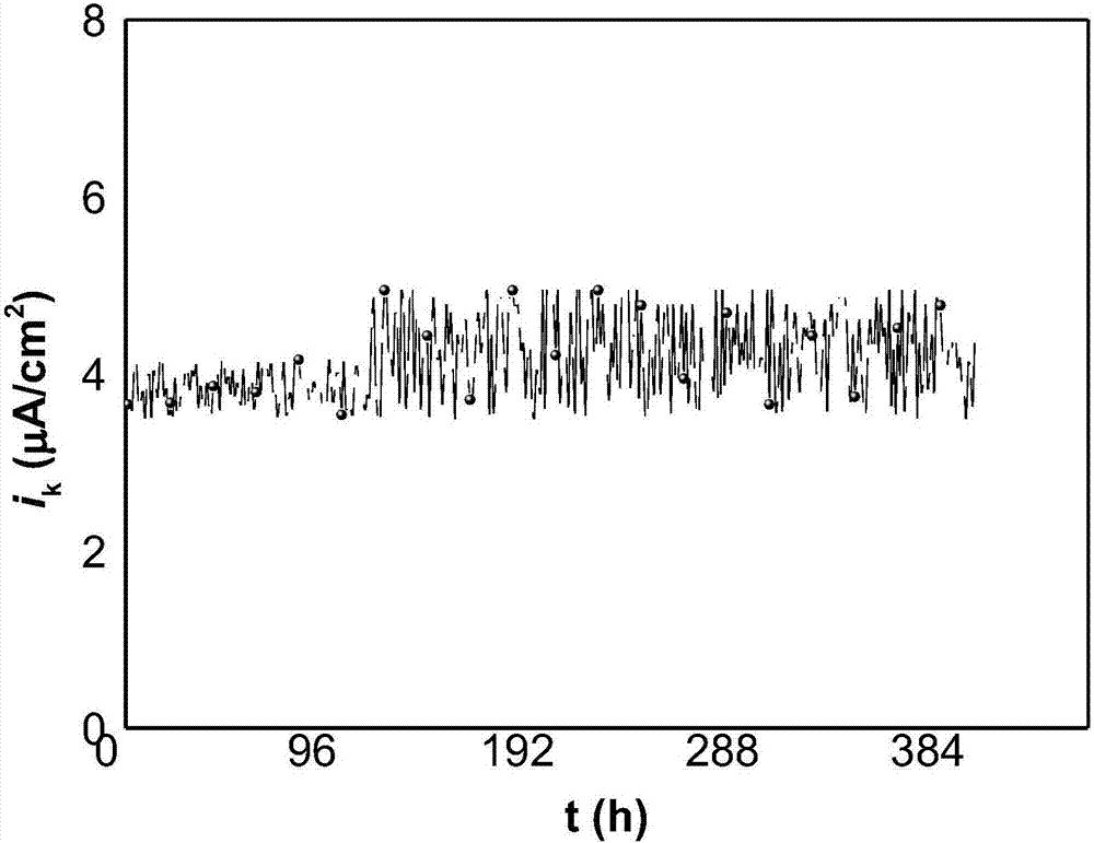
[0040] The corrosion sensor manufactured in Example 1 was placed in the atmospheric environment of Beijing, and the two wires of the corrosion sensor were respectively connected to the working electrode and the auxiliary electrode of the commercially available PS268A potentiostat. The following automatic tests are realized through a simple program on the computer side:

[0041] Test 1 is, first, control the potentiostat to input a 20mV DC voltage signal, and automatically collect the output current signal i in the loop through the device a After the test is completed, wait for 15 minutes and then control the potentiostat to input a -20mV DC voltage signal again, and automatically collect the output current signal i in the loop through the device c , collected i a and i c The value is calculated by a simple program on the computer according to the formula "i k =(i a × i c ) / (i c -i a )” to calculate the parameter i that characterizes the corrosivity of the environment k...


PUM

PropertyMeasurementUnit
thicknessaaaaaaaaaa
widthaaaaaaaaaa
thicknessaaaaaaaaaa

Abstract

The invention discloses a method for continuously monitoring corrosivity of a field environment by utilizing a corrosion sensor, and belongs to the field of atmosphere corrosion monitoring. The method comprises the following steps: firstly, selecting metal which can generate a response in time when the environment corrosivity is changed to prepare the corrosion sensor; then converting data recorded by the corrosion sensor into parameters representing the environment corrosivity, transmitting the parameters to an electrochemical workstation, controlling the electrochemical workstation to constantly input a direct current voltage signal (delta E), and recording an output current signal ia in a loop; controlling the electrochemical workstation again to constantly input a negative value (-delta E) of the direct current voltage signal after the test is completed for a period of time, and recording an output current signal ic in the loop. By using an ik value calculated by an equation that ik is equal to (ia multiplies by ic) / (ic minus ia) as a y-coordinate and testing time as an x-coordinate, a curve of ik and time is drawn; continuous monitoring on the corrosivity of the field environment can be realized according to the curve. The method disclosed by the invention has the characteristics that the service life is long and the corrosivity of the environment can be truly represented according to the monitoring data, and atmosphere corrosion behaviors in different regions of the country can be monitored for a long time.

Description

technical field [0001] The invention belongs to the field of atmospheric corrosion monitoring, and in particular provides a sensing method for continuously monitoring the corrosiveness of the field environment by using a corrosion sensor. Background technique [0002] The economic losses caused by atmospheric corrosion of metal materials in my country amount to hundreds of billions of yuan every year. It is of great significance to carry out data accumulation and regular research on atmospheric corrosion of metal materials to improve their safety and life and reduce the resulting economic losses. Metal materials have different corrosion characteristics in different corrosive field environments, so the acquisition of field atmospheric environment corrosion can provide data support for the design of anti-corrosion materials for major projects. [0003] To evaluate whether a field environmental corrosion monitoring technology is scientific and effective, there are two main indi...

Claims


Application Information

Patent Timeline
Patent Type & Authority Applications(China)
IPC IPC(8): G01N17/00
CPCG01N17/006G01N17/02
Inventor 李晓刚程学群肖葵董超芳胡为峰
Owner 浙江钱浪智能信息科技有限公司
Learn More