
Microphone array signal processing system and method

A microphone array and signal processing technology, which is applied in the direction of electrical digital data processing, transducer circuits, instruments, etc., can solve the problems of inflexible application, high cost, and complex system, so as to improve processing efficiency, improve receiving speed, and apply broad effect

Inactive Publication Date: 2017-11-21
BEIJING INTELLIGENT STEWARD CO LTD
View PDF6 Cites 7 Cited by
  • Summary
  • Abstract
  • Description
  • Claims
  • Application Information

AI Technical Summary

Problems solved by technology

In the process of processing multi-channel audio signals, there are problems such as system complexity, high circuit cost, and inflexible applications.
[0004] In the prior art, XMOS is often used for multi-channel pulse density modulation (Pulse Density Modulation, PDM) microphone data aggregation, but XMOS is a multi-core microcontroller unit (Microcontroller Unit, MCU) system, when doing multi-channel PDM interface microphone data aggregation, A decimation filter is required to restore the microphone data. This solution has high cost, high power consumption, and complex system. Using a multi-core MCU to complete this work is an overkill.
There are also processor platforms with multi-channel integrated circuit built-in audio bus (Inter-IC Sound, I2S) input to complete the acquisition of multi-channel microphone data, but there are not many processor platforms with multiple I2S inputs at present, such as: Rockchip’s RK3229 and Amlogic’s S905D, etc. The problem with this solution is that the solution is only applied to the corresponding fixed platform. Once it is replaced with another platform, the whole solution cannot be used.

Method used


Image

  • Microphone array signal processing system and method
  • Microphone array signal processing system and method
  • Microphone array signal processing system and method

Examples


Embodiment 1

[0037] figure 1 It is a structural block diagram of a microphone array signal processing system provided in Embodiment 1 of the present invention. like figure 1 As shown, the system includes: FPGA120, CPU130, main I2S, sub-I2S and microphone array 110, wherein:

[0038] The microphone array 110 is used to obtain the first analog audio data in the environment, and convert the first analog audio data into the first digital audio data, and send it to the FPGA 120; the FPGA 120 is connected to the microphone array 110 through a sub-I2S, and is used to receive the The first digital audio data of at least one path sent by the array 110, and the first digital audio data are sent to the CPU 130; the CPU 130 is connected to the FPGA through the main I2S, and is used to receive the first digital audio data sent by the FPGA 120, and send the first digital audio data to the CPU 130; The digital audio data is filtered and denoised to obtain the second digital audio data; wherein, the mai...

Embodiment 2

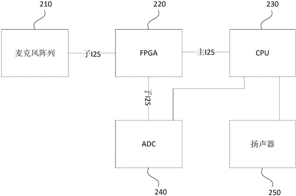
[0045] figure 2 It is a structural block diagram of a microphone array signal processing system provided in Embodiment 2 of the present invention. On the basis of the above embodiments, an ADC and a loudspeaker are added, a noise reduction signal is introduced, and the CPU data processing speed is improved. The system includes: FPGA 220, CPU 230, main I2S, sub I2S, microphone array 210, ADC 240 and speaker 250, wherein:

[0046] The CPU 230 is also used to: convert the second digital audio data into second analog audio data, and send the second analog audio data to the ADC 240 and the speaker 250;

[0047] ADC 240, connected with CPU 230 and FPGA 220, for obtaining the second analog audio data sent by CPU 230, and converting the second analog audio data into third digital audio data, and sending the third digital audio data to FPGA220, The FPGA 220 aggregates the third digital audio data and the first digital audio data and sends them to the CPU 230;

[0048] The speaker i...

Embodiment 3

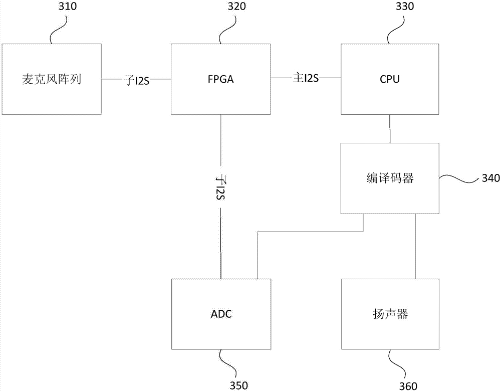
[0056] image 3 It is a structural block diagram of a microphone array signal processing system provided by Embodiment 3 of the present invention. On the basis of the above embodiments, the output of the system analog signal is specifically optimized. The system includes: FPGA320, CPU330, main I2S, sub-I2S, microphone array 310, codec 340, ADC350 and loudspeaker 360, wherein:

[0057] A codec 340, connected to the CPU 330, receives the second digital audio data sent by the CPU 330, decodes the second digital audio data, obtains the third analog audio data, and sends the third analog audio data to the ADC 350 and the speaker 360;

[0058] The ADC 350 is connected to the codec 340 and the FPGA 320, and is used to acquire the third analog audio data sent by the codec 340, convert the third analog audio data into fourth digital audio data, and send the fourth digital audio data For the FPGA 320, the FPGA 320 is used to gather the fourth digital audio data and the first digital a...


PUM


Abstract

The invention discloses a microphone array signal processing system and method. The system comprises a FPGA, a CPU, a main I2S, a sub I2S and a microphone array, wherein the FPGA is connected with the microphone array through the sub I2S; the CPU is connected with the FPGA through the main I2S, and the sampling frequency of the main I2S is the integral multiple of the sub I2S. The parallel processing on the multiple microphone array data is realized through the FPGA, the convergence capacity on the microphone data by the system is improved; the audio data is coded through the FPGA , the CPU directly processes the coded data, and the processing speed of the CPU is improved; the main I2S sampling frequency is the integral multiple of the sub I2S, so that the multiple audio data converged by the FPGA can be effectively transmitted to the CPU, and the audio data receiving speed is improved. By using the FPGA, the scheme that the multi-core processor XMOS or the I2Splatform is used for performing the data convergence of the multiple microphone array data in the prior art is overcome, and the system cost and consumption are reduced.

Description

technical field [0001] The invention relates to the field of electrical signal processing, in particular to a microphone array signal processing system and method. Background technique [0002] In recent years, with the maturity of array signal processing technology, microphone arrays are gradually being used in voice signal processing systems such as video conferencing, large stages, vehicle systems, security control, and smart homes, and the application fields are becoming more and more extensive. [0003] In the application process of the microphone array, there is a problem of inputting multiple channels of audio signals, and it is necessary to process the input multiple channels of audio signals. In the process of processing multi-channel audio signals, there are problems such as system complexity, high circuit cost, and inflexible application. [0004] In the prior art, XMOS is often used for multi-channel pulse density modulation (Pulse Density Modulation, PDM) micro...

Claims


Application Information

Patent Timeline
Patent Type & Authority Applications(China)
IPC IPC(8): H04R3/00G06F13/42
CPCG06F13/4282G06F2213/0016H04R3/00
Inventor 朱峰孙荣
Owner BEIJING INTELLIGENT STEWARD CO LTD
Learn More