
Construction method for novel drilling structure for in-situ leaching of uranium

A construction method and in-situ leaching uranium mining technology are applied in drilling equipment and methods, mining fluids, earth-moving drilling, etc., and can solve the problems of long construction period, high labor intensity for well cleaning, poor sediment resistance, etc. The effect of long construction period

Active Publication Date: 2017-11-21
中核通辽铀业有限责任公司
View PDF10 Cites 20 Cited by
  • Summary
  • Abstract
  • Description
  • Claims
  • Application Information

AI Technical Summary

Problems solved by technology

[0004] The object of the present invention is to provide a new drilling structure construction method for in-situ leaching mining of uranium, which can improve the "quality improvement, efficiency increase, and consumption reduction" of drilling construction, so as to solve the problems of long construction period and long construction period in the current drilling construction technology. Problems such as poor anti-sediment performance, low drilling success rate, labor-intensive well cleaning, high cost and poor construction quality

Method used


Image

  • Construction method for novel drilling structure for in-situ leaching of uranium
  • Construction method for novel drilling structure for in-situ leaching of uranium

Examples


Embodiment 1

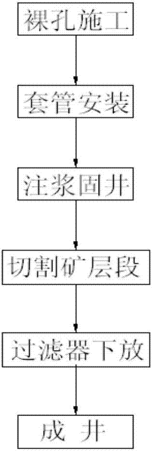
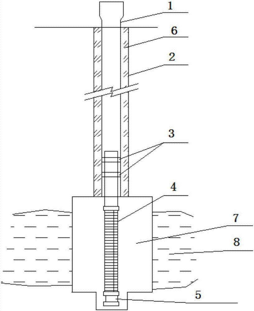
[0025] Such as Figure 1 to Figure 2 Shown, a kind of in-situ leaching mining uranium novel drilling structure construction method of the present invention, it comprises the following steps:

[0026] (a) Open hole drilling uses a Φ215mm drill bit to open the hole, drills to the upper 8m of the ore seam, replaces the Φ151mm drill bit, and drills to the design depth;

[0027] (b) After replacing the thick mud in the hole with thin mud, conduct a comprehensive exploration well, determine the position of the ore layer, determine the length of the well pipe, the position and length of the filter, and use a Φ215mm roller cone bit to ream the hole to the required depth to obtain the bare 2; The sand content of the thin mud mentioned above is 3 .

[0028] (c) After reaming, the bare hole 2 is flushed with thin mud circulation, and then the configured casings 1 are sequentially lowered into the bare hole 2; the length of the first casing at the top of the well pipe is fixed at 1 meter...

Embodiment 2

[0034] Such as Figure 1 to Figure 2 Shown, a kind of in-situ leaching mining uranium novel drilling structure construction method of the present invention, it comprises the following steps:

[0035] (a) Open hole drilling uses a Φ180mm drill bit to open the hole, drills to the upper 5m of the ore seam, replaces the Φ130mm drill bit, and drills to the design depth;

[0036] (b) After replacing the thick mud in the hole with fresh thin mud, conduct a comprehensive exploration well, determine the position of the ore layer, determine the length of the well pipe, the position and length of the filter, and use a Φ180mm roller cone bit to ream the hole to the required depth to obtain an open hole 2 ; The sand content of the fresh thin mud is less than 5%, the viscosity is less than 30s, and the density is 1.0g / cm 3 .

[0037] (c) After reaming, the bare hole 2 is flushed with thin mud circulation, and then the configured casing 1 is sequentially lowered into the bare hole 2; the l...

Embodiment 3

[0043] Such as Figure 1 to Figure 2 Shown, a kind of in-situ leaching mining uranium novel drilling structure construction method of the present invention, it comprises the following steps:

[0044] (a) Open hole drilling uses a Φ230mm drill bit to open the hole, drills to the upper 10m of the ore seam, replaces the Φ170mm drill bit, and drills to the design depth;

[0045] (b) After replacing the thick mud in the hole with fresh thin mud, carry out a comprehensive exploration well, determine the position of the ore layer, determine the length of the well pipe, the position and length of the filter, and use a Φ230mm roller cone bit to ream the hole to the required depth to obtain the open hole 2; The sand content of the fresh thin mud is 3 .

[0046] (c) After reaming, the bare hole 2 is flushed with thin mud circulation, and then the configured casing 1 is sequentially lowered into the bare hole 2; the length of the first casing at the top of the well pipe is fixed at 1.2 m...


PUM

PropertyMeasurementUnit
widthaaaaaaaaaa

Abstract

The invention provides a construction method for a novel drilling structure for in-situ leaching of uranium. The construction method comprises the following steps of: (a), drilling open holes until 5-10m of the upper part of an ore bed, and replacing a drill bit to drill to designed depth; (b) replacing mud in holes with thin mud, performing comprehensive detection on a well, determining the position of the ore bed, determining length of a well tube, determining the positions and the length of filters, and using a roller bit to expand to required design, thereby obtaining the open holes; (c), after expanding is ended, using a thin mud pump to flush the open holes in a circulating mode, and sequentially introducing configured sleeves into the open holes in sequence; (d), injecting common silicate cement paste into outside-sleeve ring-shaped space from the bottoms of the sleeves to seal the holes, thereby completing grouting and well-cementing operation; (e), performing cement grouting and well-cementing for 16-18 hours, and cutting an ore-bed section, thereby forming an ore-bed cutting section; and (f), putting the filters into the sleeves until the ore-bed section after cutting is completed. The construction method solves the defects in the prior art, and realizes upgrading, efficiency-increasing and consumption-reducing of drilling construction.

Description

technical field [0001] The invention belongs to the technical field of uranium ore leaching technology, and in particular relates to a construction method of a new drilling structure for in-situ leaching mining of uranium. Background technique [0002] In-situ leaching technology drilling is the only channel for leaching agent to enter the sandstone uranium deposit and leachate is lifted to the surface. It controls the distribution and migration of the injected leaching agent in the ore-bearing aquifer and determines whether the leaching agent can fully It reacts with uranium minerals in the ore seam, the degree of dilution of the leaching solution by groundwater, and whether the groundwater environment causes pollution and the degree of pollution. At the same time, the construction cost and quality of in-situ leaching drilling largely determine the technical and economic feasibility, rationality and effectiveness of in-situ leaching mining. Therefore, improving the drillin...

Claims


Application Information

Patent Timeline
Patent Type & Authority Applications(China)
IPC IPC(8): E21B7/00E21B7/20E21B7/28E21B21/00E21B33/13E21B43/08E21B29/06E21B33/12C04B28/04
CPCC04B28/04E21B7/00E21B7/20E21B7/28E21B21/00E21B29/06E21B33/12E21B33/13E21B43/08C04B18/0418
Inventor 苏学斌张勇汤庆四李喜龙张渤高险峰马连春曹俊鹏赵生祥
Owner 中核通辽铀业有限责任公司
Learn More