
Dual-mode synchronous rectification control circuit for DCM and CCM

A control circuit and synchronous rectification technology, which is applied in the direction of control/regulation system, electrical components, and adjustment of electrical variables, etc., can solve problems such as false opening of synchronous rectifier tubes, reduced rectification efficiency, and reduced rectification efficiency

Active Publication Date: 2017-11-14
UNIV OF ELECTRONICS SCI & TECH OF CHINA
View PDF5 Cites 17 Cited by
  • Summary
  • Abstract
  • Description
  • Claims
  • Application Information

AI Technical Summary

Problems solved by technology

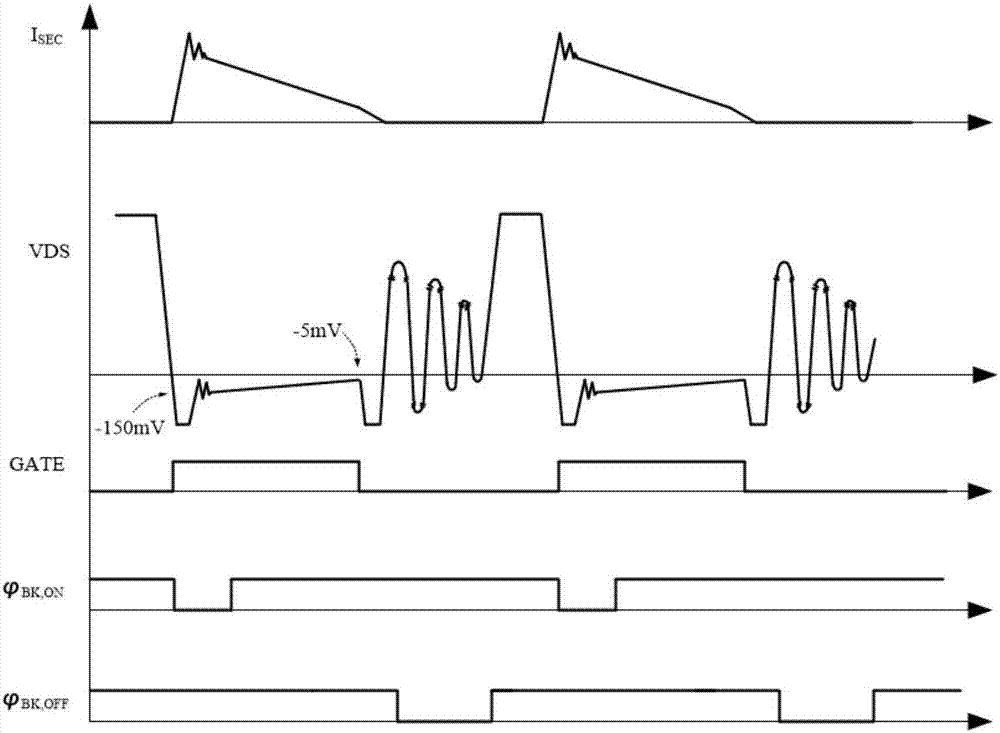
In addition, when the synchronous rectifier M2 is turned off, the drain (VD terminal) of the synchronous rectifier M2 will cause the VD voltage to ring due to LC oscillation, and the VD ringing voltage may cause 1) the synchronous rectifier is turned on by mistake, Reduce the rectification efficiency; 2) The internal devices of the rectifier chip are broken down by high voltage
For the former, a TON / TOFF signal is usually used to shield the false shutdown / turn-on, while for the latter, the traditional method is to clamp the VD sampling terminal with a Zener tube, and clamp the VD voltage when the Zener tube breaks down. It is at a safe level, but this scheme will cause the power supply to discharge current to the ground through the breakdown Zener tube, resulting in a reduction in rectification efficiency

Method used


Image

  • Dual-mode synchronous rectification control circuit for DCM and CCM
  • Dual-mode synchronous rectification control circuit for DCM and CCM
  • Dual-mode synchronous rectification control circuit for DCM and CCM

Examples


Embodiment Construction

[0045] Below in conjunction with accompanying drawing, describe technical scheme of the present invention in detail:

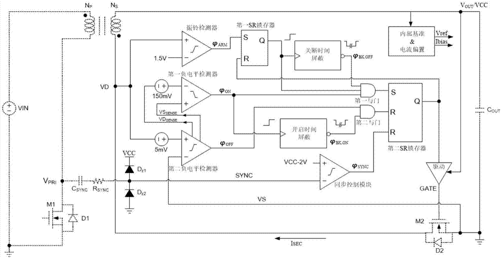
[0046] Taking the dual-mode synchronous rectification control circuit suitable for DCM and CCM proposed by the present invention as an example when it is applied to a flyback converter flyback, such as figure 1 , wherein the solid line part is the circuit topology of the present invention, which consists of an internal reference and current bias module, a ringing detector, a first negative level detector, a second negative level detector, a first SR latch, a second Two SR latches, off-time mask module, on-time mask module, synchronous control module, first AND gate, second AND gate, first Zener tube D Z1 , the second Zener tube D Z2 , drive module, the first sampling terminal samples the drain level VD of the synchronous rectifier M2 in the flyback converter, the second sampling terminal samples the source level of the synchronous rectifier M2, and the input ...


PUM


Abstract

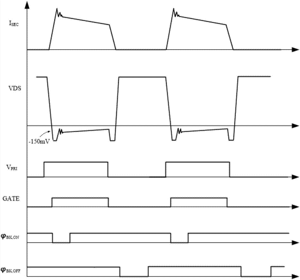
The invention provides a dual-mode synchronous rectification control circuit for a DCM and a CCM, belonging to the technical field of power management. The structure of the circuit is simple, the rectification conduction loss can be effectively reduced, and high efficiency of synchronous rectification is realized. Minimum dead time control is realized by a second negative level detector. A turn-off time shielding module prevents the wrong turn-on of a synchronous rectifier tube M2, and a turn-on time shielding module prevents the wrong turn-off of the synchronous rectifier tube M2. Drain electrodes of LDMOS and DEMOS high voltage devices are used by a first sampling end to bear high voltage, the clamping of a drain end VD of the synchronous rectifier tube M2 by a Zener is avoided, and the current leakage to the ground by the drain end VD of the synchronous rectifier tube M2 is prevented. The high efficiency of synchronous rectification is realized by the above measures together. In addition, a synchronous control module is introduced, and the synchronous rectification in a current continuous mode CCM is realized.

Description

technical field [0001] The invention belongs to the technical field of power management, and in particular relates to a dual-mode synchronous rectification control circuit suitable for DCM and CCM. Background technique [0002] As the size of modern high-speed VLSI continues to decrease, the power consumption continues to decrease, the required power supply voltage is also getting lower and lower, and the output current is getting higher and higher. In the low-voltage and high-current output environment, the conduction voltage drop of traditional rectifier diodes is high. Even if a low-drop Schottky diode is used, a voltage drop of more than 0.4V will occur, resulting in increased rectification losses and reduced power supply efficiency. Synchronous rectification technology can greatly reduce the power consumption of the rectification part by using MOSFETs with lower on-resistance, improve the performance of the converter, and achieve high efficiency of the power supply. ...

Claims


Application Information

Patent Timeline
IPC IPC(8): H02M7/217H02M3/335H02M1/08H02M1/32
CPCH02M1/08H02M1/32H02M3/33592H02M7/217H02M1/0054H02M7/2195Y02B70/10
Inventor 明鑫张文林鲁信秋张宣王卓张波
Owner UNIV OF ELECTRONICS SCI & TECH OF CHINA
Learn More