Stamping die

A technology of stamping dies and dies, which is applied in the direction of perforating tools, manufacturing tools, metal processing equipment, etc., can solve the problems of warping at both ends of the workpiece, and achieve the effect of avoiding turbine rotation, good effect and high degree of automation

Active Publication Date: 2017-11-14
常熟市明光冲压件有限公司
View PDF9 Cites 10 Cited by
  • Summary
  • Abstract
  • Description
  • Claims
  • Application Information

AI Technical Summary

Problems solved by technology

[0005] The purpose of the present invention is to provide a stamping die to solve the problem that the two ends of the workpiece are lifted during stamping

Method used


Image

  • Stamping die
  • Stamping die
  • Stamping die

Examples


Embodiment Construction

[0022] The present invention will be described in further detail below by means of specific embodiments:

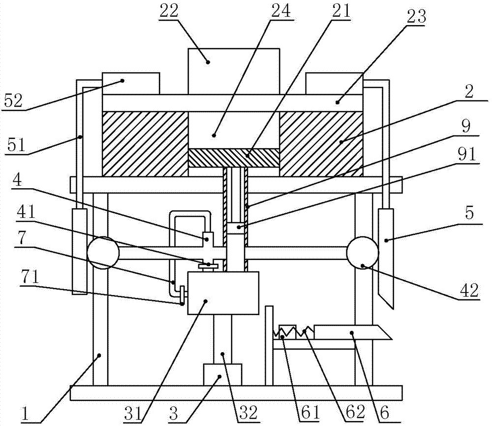
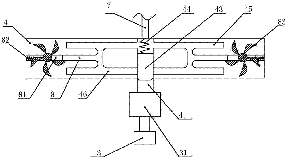
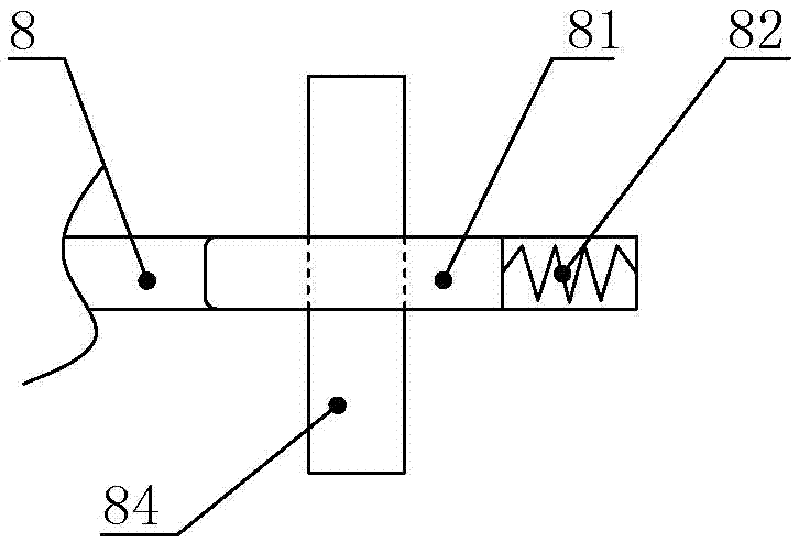
[0023] The reference signs in the drawings of the description include: frame 1, upper mold 2, lower mold 21, punch 22, workpiece 23, mold cavity 24, steam generator 3, booster pump 31, air pipe 32, main pipe 4, the first A valve 41, a gear 42, a slide plate 43, a first spring 44, a first air passage 45, a second air passage 46, a rack 5, a connecting rod 51, a pressing block 52, a wedge bar 6, a switch 61, and a third spring 62 , branch pipe 7, second valve 71, third air passage 8, latch 81, second spring 82, turbine 83, turbine shaft 84, conduit 9, slide block 91.

[0024] The embodiment is basically as shown in the accompanying drawings

[0025] Such as figure 1 As shown, a stamping die of the present invention includes a frame 1, an upper mold 2 is arranged on the frame 1, a mold cavity 24 is opened in the middle of the upper mold 2, and a lower mold 21 is slidably a...


PUM


Abstract

The invention relates to the technical field of metal forging, in particular to a stamping die. The stamping die comprises an upper die body. A lower die body is arranged in a die cavity. A steam generator and a booster pump are arranged below the lower die body. The booster pump communicates with a main pipe. The main pipe communicates with a branched pipe, and the branched pipe communicates with the booster pump. A sliding plate is slidably arranged in the main pipe. A first spring is connected between the sliding plate and the wall of the main pipe. A turbine is arranged in the main pipe. A first air duct and a second air duct are formed in the main pipe, and an air outlet of the first air duct and an air outlet of the second air duct face two symmetrical sides of the turbine correspondingly. A third air duct is formed between the first air duct and the second air duct in a communicating mode. A plug pin is slidably arranged in the third air duct, a second spring is connected between the plug pin and the wall of the third air duct, and the plug pin is slidably arranged on a turbine shaft of the turbine. The turbine is coaxially connected with gears, the gears are engaged with racks, the racks are connected with connecting rods, and the connecting rods are connected with pressing blocks used for pressing the two ends of a workpiece. By adoption of the stamping die, the problem that the two ends of the workpiece warp upwards in the stamping process is solved.

Description

technical field [0001] The invention relates to the technical field of metal forging, in particular to a stamping die. Background technique [0002] Traditionally used stamping dies usually use guide posts and guide sleeves to assist mold clamping. In this way of operation, due to excessive impact force, it is easy to damage the guide posts and guide sleeves, and it is very troublesome to repair the mold. [0003] In order to solve the above problems, the Chinese patent, the utility model with the authorization number CN204892697U discloses a buffer stamping die, including a moving die and a fixed die, the moving die is arranged above the fixed die, and the moving die includes a moving die seat plate and a moving die backing plate And the fixed plate of the movable mold, the bottom of the movable mold seat plate is connected with the movable mold backing plate, the bottom of the movable mold backing plate is connected with the movable mold fixed plate, buffer springs are arr...

Claims


Application Information

Patent Timeline
Patent Type & Authority Applications(China)
IPC IPC(8): B21D28/34B21D43/00
CPCB21D28/34B21D43/003
Inventor 陈文斌
Owner 常熟市明光冲压件有限公司
Why Eureka
Try Eureka