
Electric type fixture capable of achieving distance adjustment

An electric distance adjustment technology, which is applied in the field of electric distance adjustment fixtures, can solve problems such as clamping between two splints, danger, and damage to clamped objects, so as to increase flexibility and avoid personal safety issues. Effect

Pending Publication Date: 2017-11-07
屈文斌
View PDF0 Cites 11 Cited by
  • Summary
  • Abstract
  • Description
  • Claims
  • Application Information

AI Technical Summary

Problems solved by technology

[0002] Fixture refers to the device used to fix the processing object in the process of mechanical manufacturing so that it can occupy the correct position to accept construction or inspection. It is also called fixture. In a broad sense, any process in the process is used to quickly and The device that installs the workpiece conveniently and safely can be called a fixture. During the clamping process, the fixture is usually manually operated. This method of operation can easily cause the operator's body parts to be sandwiched between the two splints, causing danger. And this method of operation is time-consuming and labor-intensive; since there is no buffer pad on the inside of the splint of the fixture, it is easy to damage the clamped object

Method used


Image

  • Electric type fixture capable of achieving distance adjustment
  • Electric type fixture capable of achieving distance adjustment

Examples


Embodiment Construction

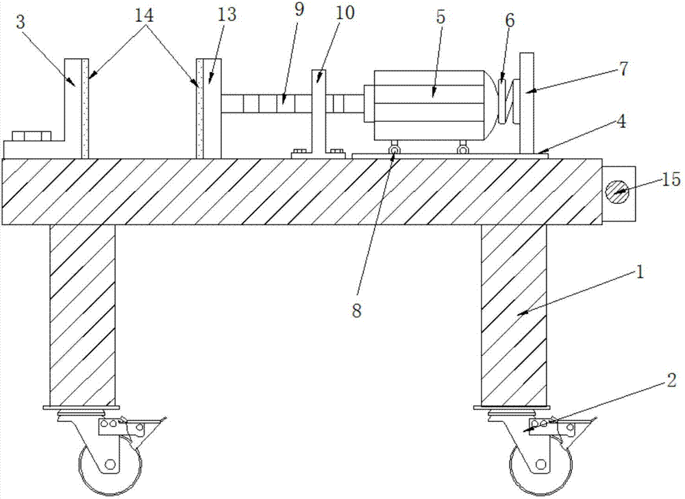
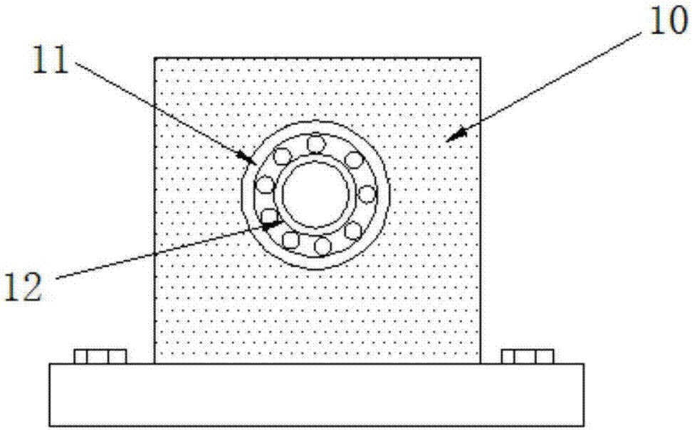
[0015] Attached below Figure 1-2 An embodiment of the present invention is described.

[0016] Electric distance adjustment fixture, including bracket 1, universal wheel 2, fixed splint 3, slide rail 4, servo motor 5, damping spring 6, limit plate 7, roller 8, threaded rod 9, support plate 10, concave Groove 11, bearing 12, movable splint 13, buffer pad 14 and power switch 15, the fixed splint 3 is installed on the left side of the upper end of the bracket 1, and the slide rail 4 is installed on the right side of the upper end of the bracket 1, and the servo motor is installed on the upper left side of the bracket 1 5. The right side of the servo motor 5 is provided with a limit plate 7, and a roller 8 is installed on the outer side of the lower end of the servo motor 5, and the outer side of the left end of the servo motor 5 is fixedly connected with a threaded rod 9, and the outer side of the middle part of the threaded rod 9 is sleeved with a support plate 10. The middle ...


PUM


Abstract

The invention provides an electric type fixture capable of achieving distance adjustment. The electric type fixture comprises a support, a fixed clamping plate, a sliding rail, a servo motor, a threaded rod, a supporting plate, a bearing, a moving clamping plate, cushion pads and a power switch, wherein the fixed clamping plate is installed on the left side of the upper end of the support, the sliding rail is installed on the right side of the upper end of the support, the servo motor is installed on the upper portion of the left side of the support, the threaded rod is fixedly connected to the outer side of the left end of the servo motor, the supporting plate is connected to the outer side of the middle of the threaded rod in a sleeving manner, the bearing is installed inside a groove, the moving clamping plate is fixedly connected to the left end of the threaded rod, and the power switch is installed on the outer side of the right end of the support. The servo motor is arranged, the distance between the two clamping plates can be adjusted in an electric manner, and the personal safety problem caused by manual adjustment is avoided; universal wheels are arranged, and therefore the fixture can be moved rapidly, and the flexibility of the fixture is improved; and the cushion pads are arranged, and therefore a clamped object can be protected from being damaged due to high-strength squeezing of the fixture.

Description

technical field [0001] The invention belongs to the field of machinery, and in particular relates to an electric distance-adjusting fixture. Background technique [0002] Fixture refers to the device used to fix the processing object in the process of mechanical manufacturing so that it can occupy the correct position to accept construction or inspection. It is also called fixture. In a broad sense, any process in the process is used to quickly and The device that installs the workpiece conveniently and safely can be called a fixture. During the clamping process, the fixture is usually manually operated. This method of operation can easily cause the operator's body parts to be sandwiched between the two splints, causing danger. And this method of operation is time-consuming and laborious; since the inside of the splint of the clamp is not provided with a buffer pad, it is easy to damage the clamped object. Contents of the invention [0003] The technical problem solved by...

Claims


Application Information

Patent Timeline
Patent Type & Authority Applications(China)
IPC IPC(8): B23Q3/06B25B11/00
CPCB23Q3/06B25B11/00
Inventor 屈文斌
Owner 屈文斌
Learn More