
Wet etching equipment

A technology of wet etching and equipment, which is applied in the field of flat-panel display manufacturing. It can solve the problems of uneven flow of liquid medicine, easy occupation of space, and different overlapping areas, so as to reduce the generation of mura, reduce cost and time, and reduce the number of machines. structure effect

Active Publication Date: 2020-01-31
TCL CHINA STAR OPTOELECTRONICS TECH CO LTD
View PDF4 Cites 0 Cited by
  • Summary
  • Abstract
  • Description
  • Claims
  • Application Information

AI Technical Summary

Problems solved by technology

For example, for the second layer of metal, if the etching size is uneven, that is, the wires in some areas are wider, it will cause the difference in the overlapping area between the second layer of metal and the first layer of metal between pixels, that is, different The capacitive coupling effect makes the quality of the panel deviate from the design value
[0004] At present, the commonly used wet etching modes mainly include spray mode, dip mode and puddle mode. For the existing wet etching equipment, the above three etching modes need to be etched in different etching modes. It is completed in the unit, that is, the spray etching unit, soaking etching unit and coating etching unit in the existing wet etching equipment are independent etching units with separate functions. Therefore, the structure of the wet etching equipment is relatively complicated, difficult to maintain, and the machine area is large. , easy to occupy space; among them, in the Spray mode, the spray etching unit mainly realizes the oscillation (Oscillation) action to make the etching more uniform by rotating the conveying roller to transport the glass substrate on it back and forth in the horizontal direction. It will lead to scrap; in Dip mode, the immersion etching unit mainly achieves the purpose of immersion by closing the shutters (Shutter) at both ends of the etching tank, so there are two disadvantages. One is that when the Shutter is turned on, it will cause the liquid to flow unevenly and form mura. , the second is that for each piece of glass, it is necessary to perform closing and opening shutter actions, which reduces the etching efficiency; in Puddle mode, the coating and etching unit mainly uses the etching method of fixed liquid knife and moving glass substrate, so it can only perform single etching. Liquid coating

Method used


Image

  • Wet etching equipment
  • Wet etching equipment
  • Wet etching equipment

Examples


Embodiment Construction

[0024] In order to further illustrate the technical means and effects adopted by the present invention, the following describes in detail in conjunction with the embodiments of the present invention and the accompanying drawings.

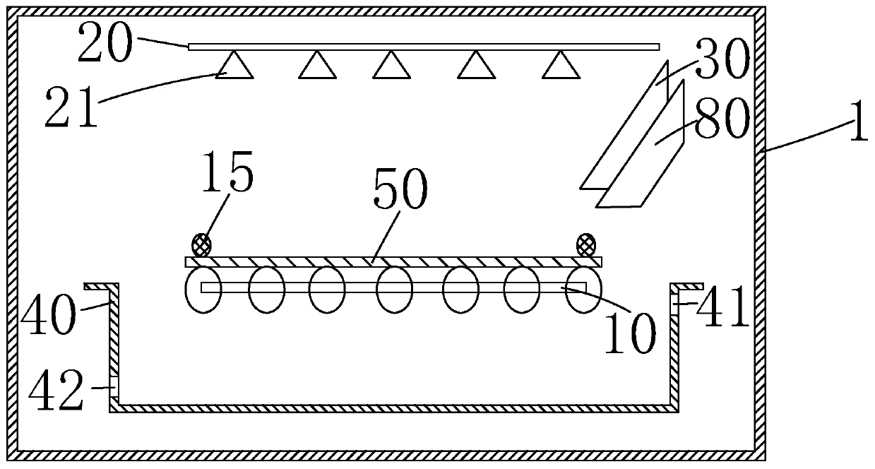
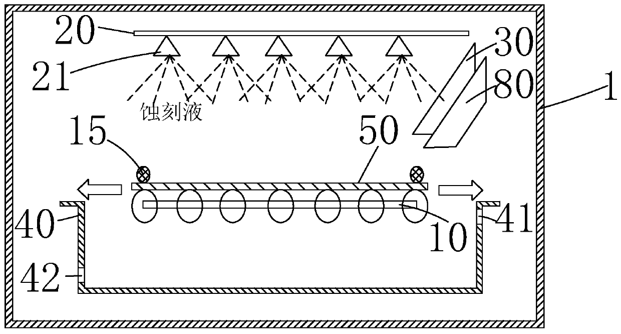
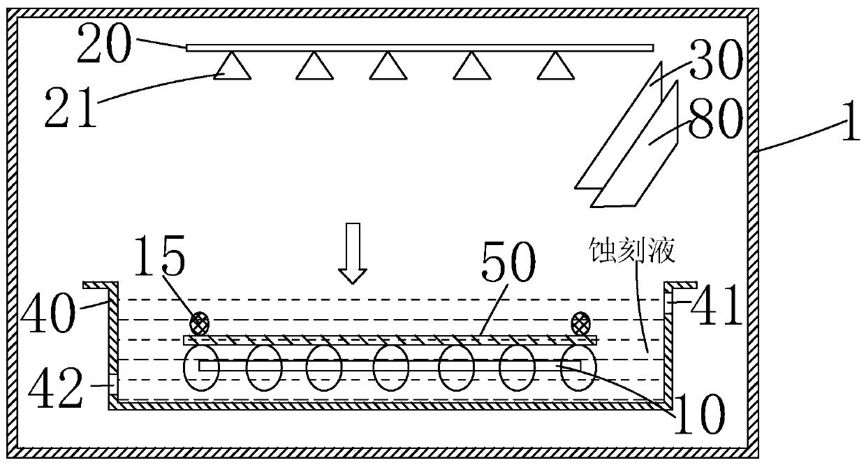
[0025] see figure 1 , the present invention provides a wet etching device, comprising an etching chamber 1, and a carrying platform 10 installed in the etching chamber 1, a spray pipe 20, a liquid knife 30, and an etching tank 40, wherein the carrying platform 10 is used On the carrier substrate 50, the spray pipe 20 is arranged above the carrier table 10 for spraying etching solution on the surface of the substrate 50, and the liquid knife 30 is arranged between the carrier table 10 and the spray pipe 20 for After coating the etching solution on the surface of the substrate 50 , the etching tank 40 is disposed under the carrier table 10 for containing the etching solution and the substrate 50 .

[0026] The wet etching equipment of the present inv...


PUM


Abstract

The invention provides wet etching equipment. The wet etching equipment comprises a bearing platform used for bearing a substrate, a spraying pipe which is arranged above the bearing platform for spraying an etching liquid to the surface of the substrate, a liquid knife which is arranged between the bearing platform and the spraying pipe and used for coating the surface of the substrate with the etching liquid, and an etching groove which is formed below the bearing platform and used for accommodating the etching liquid and the substrate; therefore, the three kinds of etching modes, including a spray mode, a dip mode and a puddle mode, can be integrated into the same etching unit, so that the machine table structure is reduced, the occupied space of the machine table is reduced, and the maintenance cost and time are lowered; and in addition, the substrate on the bearing platform moves along with the bearing platform in the etching process, without needing to transfer the substrate independently, so that the etching process is more stable, thereby reducing generation of mura.

Description

technical field [0001] The invention relates to the field of flat panel display process, in particular to a wet etching device. Background technique [0002] In the field of display technology, flat panel display devices such as Liquid Crystal Display (LCD) and Active Matrix Organic Light-Emitting Diode (AMOLED) have thin body and high image quality. , power saving, no radiation and many other advantages have been widely used, such as: mobile phones, personal digital assistants (PDA), digital cameras, computer screens or notebook screens, etc. [0003] Thin Film Transistor (Thin Film Transistor, TFT) array (Array) substrates are the main components of current LCD devices and AMOLED devices, and are directly related to the development direction of high-performance flat panel display devices. For example, the LCD manufacturing process generally includes: the front-end array process, the middle-end cell (Cell) process, and the back-end module assembly process, and the front-en...

Claims


Application Information

Patent Timeline
Patent Type & Authority Patents(China)
IPC IPC(8): H01L21/67
CPCH01L21/67075H01L21/6708
Inventor 尹易彪
Owner TCL CHINA STAR OPTOELECTRONICS TECH CO LTD
Learn More