Thermally stable spin-orbit torsion magnetic random access memory

A technology of spin-orbit and thermal stability, applied in static memory, digital memory information, information storage, etc., can solve problems such as insufficient thermal stability, and achieve the effect of solving insufficient thermal stability and simplifying the MRAM manufacturing process

Active Publication Date: 2019-04-12
赖志煌
View PDF5 Cites 0 Cited by
  • Summary
  • Abstract
  • Description
  • Claims
  • Application Information

AI Technical Summary

Problems solved by technology

[0009] The purpose of the present invention is to provide a thermally stable spin-orbit torsion magnetic flash memory that can simplify the MRAM manufacturing process and solve the problem of insufficient thermal stability

Method used


Image

  • Thermally stable spin-orbit torsion magnetic random access memory
  • Thermally stable spin-orbit torsion magnetic random access memory
  • Thermally stable spin-orbit torsion magnetic random access memory

Examples


specific example 1

[0061] A specific example 1 (E1) of the thermally stable spin-orbit torsion RAM of the present invention is substantially the same as the comparative example 1 (CE1), the difference being that the specific example 1 ( E1) is an Ir with a thickness of 8nm 20 mn 80 The alloy film is used as a second metal film of a magnetic free layer of the specific example 1 (E1); that is, a multilayer film formed on a silicon wafer of the specific example 1 (E1) is Ta(2.5 nm) / Pt(2nm) / Co(1.17nm) / Ir 20 mn 80 (8nm) / Pt(4nm) / Ta(2.5nm); and the magnetic free layer is Pt(2nm) / Co(1.17nm) / Ir 20 mn 80 (8nm).

specific example 2

[0063] A specific example 2 (E2) of the thermally stable spin-orbit torsion RAM of the present invention is substantially the same as the comparative example 1 (CE1), and the difference is that the specific example 2 ( E2) is an Ir with a thickness of 10nm 20 mn 80 The alloy film is used as a second metal film of a magnetic free layer of the specific example 2 (E2); that is, a multilayer film formed on a silicon wafer of the specific example 2 (E2) is Ta(2.5 nm) / Pt(2nm) / Co(1.17nm) / Ir 20 mn 80 (10nm) / Pt(4nm) / Ta(2.5nm); and the magnetic free layer is Pt(2nm) / Co(1.17nm) / Ir 20 mn 80 (10nm).

specific example 3

[0067] A specific example 3 (E3) of the thermally stable spin-orbit torsion RAM of the present invention is substantially the same as the comparative example 2 (CE2), and the difference is that the specific example 3 ( E3) is an Ir with a thickness of 8nm 20 mn 80 The alloy film is used as a second metal film of a magnetic free layer of the specific example 3 (E3); that is, a multilayer film formed on a silicon wafer of the specific example 3 (E3) is Ta (2.5 nm) / Pt(2nm) / Co(0.88nm) / Ir 20 mn 80 (8nm) / Pt(4nm) / Ta(2.5nm); and the magnetic free layer is Pt(2nm) / Co(0.88nm) / Ir 20 mn 80 (8nm).

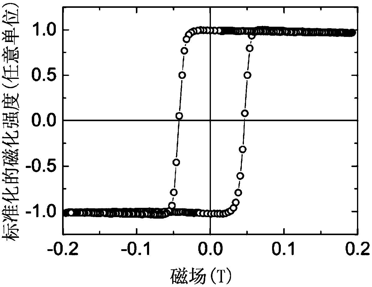
[0068] see again Figure 4 and Figure 5 , what needs to be further supplemented here is that when the present invention writes the comparative examples (CE1-CE2) and the specific examples (E1-E3) to analyze their magnetic properties, it uses a focusing vertical magneto-optical gram The focused polar magneto-optical Kerr effect system (focused polar magneto-optical Kerr effect system; h...


PUM


Abstract

A thermally stable spin-orbit torsion magnetic flash memory, comprising a substrate and a spin-orbit torsion memory cell arranged on the substrate and having a magnetic free layer. The magnetic free layer includes a ferromagnetic first metal film, second and third metal films which are in contact with the first metal film and exhibit antiferromagnetism and spin Hall effect respectively. The first metal film has a first thickness between 0.5-1.5nm. The second metal film has an exchange offset field H sufficient to provide the magnetic free layer EB and greater than the second thickness of 6 nm. h EB It is formed when an external magnetic field and an AC pulse electric signal are provided to the magnetic free layer along a hard axis of the first metal film to reach a critical current density generated by the AC pulse electric signal. The second metal film is an IrMn alloy film without vertical field annealing and without vertical field plating. The magnetic free layer essentially has a coercive field (H C ), and |H EB |>|H C |.

Description

technical field [0001] The present invention relates to a magnetic random-access memory (magnetoresistive random-access memory, hereinafter referred to as MRAM), in particular to a spin-orbit torsion magnetic random-access memory with thermal stability (hereinafter referred to as MRAM) SOT-MRAM). Background technique [0002] Based on the discovery of the tunneling magnetoresistance (TMR) effect, a ferromagnetic free layer, an extremely thin insulating barrier layer and a ferromagnetic pinned layer ) composed of magnetic random access memory (MRAM), can quickly flip the magnetic moment of the ferromagnetic free layer through the spin characteristics of electrons and cooperate with current and external magnetic field, so that the MARM The resistance value can be changed through the relationship between the magnetic moment arrangement in the free layer and the fixed layer, so as to identify two signals of 0 and 1 of MARM. Therefore, MRAM has been recognized as the next gener...

Claims


Application Information

Patent Timeline
Patent Type & Authority Patents(China)
IPC IPC(8): H01L43/02H01L43/08B82Y40/00
CPCB82Y40/00H10N50/80H10N50/10G11C11/1675G11C11/18G11C11/161H10N50/85H10B61/00H10N52/80H10N52/00
Inventor 赖志煌蔡明翰黄国峰
Owner 赖志煌
Why Eureka
Try Eureka