
Dry etching equipment and etching method

A dry etching and equipment technology, used in electrical components, semiconductor/solid-state device manufacturing, circuits, etc., can solve problems such as extremely high requirements for cleanliness, increased manufacturing costs, and short maintenance cycles, and reduces requirements for cleanliness , The effect of maximizing production efficiency and prolonging maintenance cycle

Inactive Publication Date: 2017-10-27
WUHAN CHINA STAR OPTOELECTRONICS TECH CO LTD
View PDF3 Cites 2 Cited by
  • Summary
  • Abstract
  • Description
  • Claims
  • Application Information

AI Technical Summary

Problems solved by technology

This method replaces aluminum fluoride with aluminum chloride before the dry etching process and then exhausts it, which is equivalent to cleaning the cavity before the dry etching process, and then removing aluminum chloride in the fluorine-chlorine replacement process. It is replaced by aluminum fluoride, and aluminum fluoride crystals will still remain in the cavity. The process is complicated and cumbersome, which increases the manufacturing cost, the process is complicated, the production efficiency is extremely low, and there will still be a lot of aluminum chloride remaining in the exhaust. After the fluorine replacement, the aluminum fluoride grains remain in the cavity. The fluorine replacement and main etching processes are all in the same cavity. The accumulation of aluminum fluoride crystals inevitably affects the cleanliness of the cavity, which is fundamentally unavoidable. The aluminum fluoride crystal hinders the etching of the aluminum metal layer by chlorine gas, which ultimately affects the product yield. It can be seen that this method cannot completely solve the impact caused by the residual aluminum fluoride
[0011] None of the three methods mentioned in the above patent documents can completely solve the impact caused by residual aluminum fluoride, the product yield is low, and the main etching process and fluorine replacement process are carried out in the same chamber, which requires extremely high cleanliness , which makes the maintenance cycle of the equipment short, increases the cost, and also causes the problems of low production efficiency and low equipment capacity

Method used


Image

  • Dry etching equipment and etching method
  • Dry etching equipment and etching method
  • Dry etching equipment and etching method

Examples


Embodiment 1

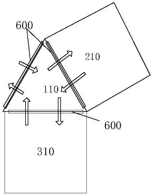
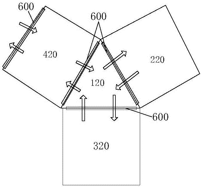
[0047] Please refer to figure 1 , Embodiment 1 of the dry etching equipment of the present invention, which includes: a main etching process chamber 210, a post-processing process chamber 310, and a transfer chamber 110, the main etching process chamber 210 and the post-processing process 310 chambers are respectively The transfer chamber 110 is connected and communicated through an openable and closable chamber door 600 , and the transfer chamber 110 is further provided with an openable and closable chamber door 600 to communicate with the outside world.

[0048] Such as figure 1 The product operation flow shown by the arrow, when performing etching treatment, the product to be processed first enters the transfer chamber 110, and then is transported by the transfer chamber 110 to a separate main etching process chamber 210 for the main etching process, and the post-processing process is carried out in another post-processing chamber. The processing is carried out in the proc...


PUM


Abstract

The invention provides dry etching equipment which comprises at least one main etching process cavity and a post-processing process cavity separated from each other. In the main etching process cavity, a chlorine containing etching medium is used to etch a product to be processed, in the post-processing process cavity, a fluorine containing placement medium is used to replace residue chlorine ions on the etched product to be processed with fluorine ions. The method provides a dry etching method which comprises a step of conveying the product to be processed into the main etching process cavity, a step of injecting the chlorine containing etching medium into the main etching process cavity so as to etch the product to be processed, a step of conveying the etched product to be processed into the post-processing process cavity, and a step of injecting fluorine containing placement medium into the post-processing process cavity to replace the residue chlorine ions on the product to be processed with the fluorine ions. According to the dry etching equipment and method, the influence of residues on a main etching process in the prior art is solved, the yield of the product is greatly improved, the production efficiency is improved, and the equipment maintenance cycle is prolonged.

Description

technical field [0001] The invention relates to the field of display technology, in particular to a dry etching device and an etching method. Background technique [0002] In LTPS (Low Temperature Poly-silicon, low-temperature polysilicon technology) and OLED (Organic Light-Emitting Diode, organic light-emitting diode) process, SD (Source Drain line, source and drain, the main component is Al) film etching, in order to achieve CD loss (strip width loss) specifications, all adopt dry etching process to transfer the pattern on the photomask to the film layer. [0003] In the common SD dry etching process, the main etching step (Main Etch step) uses Cl2 gas. After the MainEtch step is completed, there will be residual Cl ions on the SD film layer and the PR photoresist film layer. If the residual Cl ions are not passed through The processing will react with the Al in the SD film layer in the atmospheric environment (an environment with a humidity of about 55%), resulting in Al...

Claims


Application Information

Patent Timeline
Patent Type & Authority Applications(China)
IPC IPC(8): H01L21/67
CPCH01L21/67069H01L21/67207
Inventor 方亮肖文欢
Owner WUHAN CHINA STAR OPTOELECTRONICS TECH CO LTD
Learn More