
Device and method for monitoring arrester resistance current by introducing unconventional potential transformer (PT)

A monitoring device and resistive current technology, which is applied in the direction of measuring devices, measuring current/voltage, measuring electricity, etc., can solve the problems of device introduction, lightning arrester monitoring device can not be connected to SV signal, etc., so as to prolong the maintenance cycle and improve the overall economy Efficiency, the effect of broad market application prospects

Active Publication Date: 2012-09-19
BEIJING SIFANG JIBAO AUTOMATION +1
View PDF3 Cites 19 Cited by
  • Summary
  • Abstract
  • Description
  • Claims
  • Application Information

AI Technical Summary

Problems solved by technology

[0011] For smart substations or digital substations using electronic or photoelectric PTs, in order to solve the problem that the bus voltage cannot be introduced through the bus voltage extraction device and the problem that the traditional lightning arrester monitoring device cannot be connected to the SV signal, the present invention proposes a method for introducing unconventional PT Method for monitoring arrester resistive current and arrester resistive current monitoring device based on unconventional PT

Method used


Image

  • Device and method for monitoring arrester resistance current by introducing unconventional potential transformer (PT)
  • Device and method for monitoring arrester resistance current by introducing unconventional potential transformer (PT)
  • Device and method for monitoring arrester resistance current by introducing unconventional potential transformer (PT)

Examples


Embodiment Construction

[0035] The technical solution of the present invention will be further described in detail below in conjunction with the accompanying drawings.

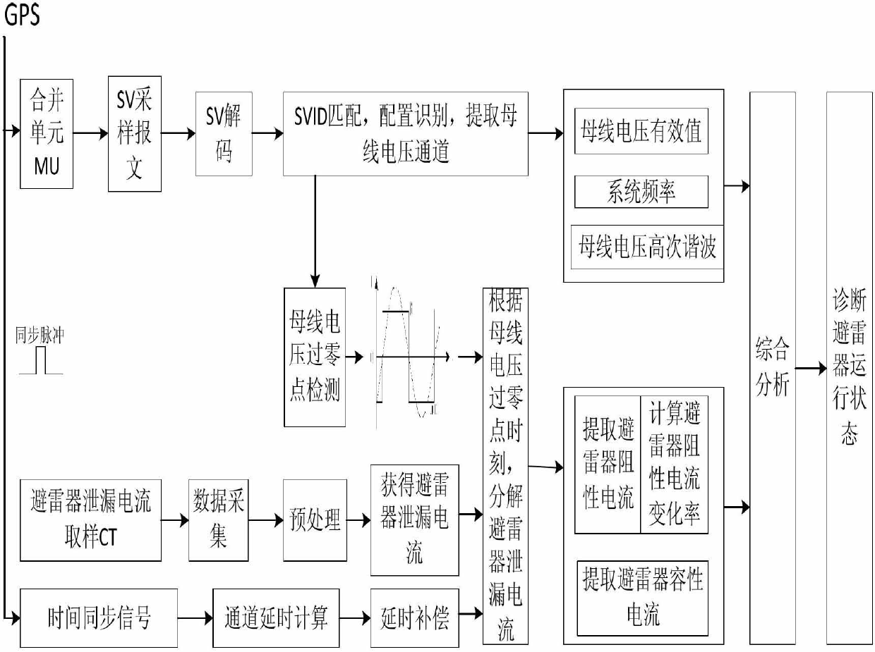
[0036] Such as figure 1 Shown is the overall structure diagram of the introduction of unconventional PT to monitor the resistive current of the arrester. The system requires the unified time synchronization of the whole station to ensure the time synchronization between the merging unit MU and the arrester monitoring device. By decoding the SV message, searching for the specified bus voltage acquisition channel, performing Fourier filter processing on the bus voltage channel, calculating voltage RMS, harmonics, system frequency and other parameters, and calculating the bus voltage zero-crossing time according to the system synchronous clock. The current sensor is used to collect the leakage current data of the arrester in real time, and the resistive current of the arrester is calculated according to the bus voltage phase. According...


PUM


Abstract

The invention discloses a method and a device for monitoring arrester resistance current by introducing unconventional PT. Firstly, the monitoring device accesses sampled value (SV) messages of merging units (MU), decodes the SV messages, detects the time of zero crossing point of busbar voltage, calculates the channel delay accurately by relying on an external synchronous clock, and restores sinusoidal waveform of the busbar voltage accurately. Secondly, the monitoring device collects leakage current sensor information mounted on a grounding wire of an arrester, and decomposes the leakage current of the arrester into resistance current and capacity current. Thirdly, the monitoring device determines the operation condition of the arrester based on the change rate of the resistance current and the ratio of the resistance current value in the arrester leakage current. According to the method and the device for monitoring arrester resistance current, the problem that some online monitoring devices cannot introduce busbar voltage signals for calculating the arrester resistance current when the busbar voltage is digital signals in intelligent substations or digital substations is solved effectively, defects of early aging, insulation hidden dangers and the like of arresters can be found earlier, and application prospect in the market is broad.

Description

technical field [0001] The invention belongs to the field of power system state monitoring, and in particular relates to a method for monitoring the state of an arrester by using an unconventional PT. Background technique [0002] my country's power grid continued to maintain rapid development during the "Twelfth Five-Year Plan" period, and thousands of substations were newly built, expanded, and renovated, which provided a broad stage for the research, construction, and development of smart grids. It is against this background that smart substation and smart high-voltage equipment technologies are proposed. [0003] Zinc oxide surge arresters (MOA) have the advantages of large flow capacity, low residual voltage, fast response, long life, etc., can effectively protect power equipment, and are widely used in overvoltage protection of power systems. Since MOA has good non-linear resistance characteristics, there is no gap inside the zinc oxide arrester. It is precisely beca...

Claims


Application Information

Patent Timeline
Patent Type & Authority Applications(China)
IPC IPC(8): G01R19/175G01R31/02
Inventor 唐喜任雁铭余斌周涛李征金中华
Owner BEIJING SIFANG JIBAO AUTOMATION
Learn More