
Wire grid structure and manufacturing apparatus thereof

A technology for manufacturing devices and wire grids, which is applied in the field of wire grid structures and manufacturing devices in the terahertz band, can solve the problems of device performance not meeting application requirements, difficult processing, and narrow bandwidth, so as to avoid the influence of substrate interference, Improved polarization transmission performance and moderate processing difficulty

Inactive Publication Date: 2017-10-24
SUZHOU INST OF NANO TECH & NANO BIONICS CHINESE ACEDEMY OF SCI
View PDF8 Cites 6 Cited by
  • Summary
  • Abstract
  • Description
  • Claims
  • Application Information

AI Technical Summary

Problems solved by technology

The difference between the two is that the substrate-based polarizer has the problems of low extinction ratio, narrow bandwidth, and serious interference due to the influence of the substrate. Therefore, researchers in this field hope to obtain high-performance terahertz through continuous research. polarizer
[0007] In 2008, C.F.Hsieh et al. used the birefringence characteristics of liquid crystals to fill a layer of liquid crystals on the fused silica substrate and align them under the action of a magnetic field to prepare a Feussner type liquid crystal polarizer with a frequency of 0.2THz-1.0THz and an extinction coefficient of Up to 40dB, but the liquid crystal layer and the substrate are difficult to compress and package, and there is a large interference effect
Although the processing and preparation technology of metal wire grids without substrate support in the microwave band is very mature, there are still many problems in the preparation of substrate-free metal wire grid polarizers for the terahertz band, such as: the substrate has a high refractive index, and the interference is relatively weak. Seriously, the extinction ratio is low, the performance of the device cannot meet the application requirements, and the sample without substrate support is easy to deform and difficult to process, etc.

Method used

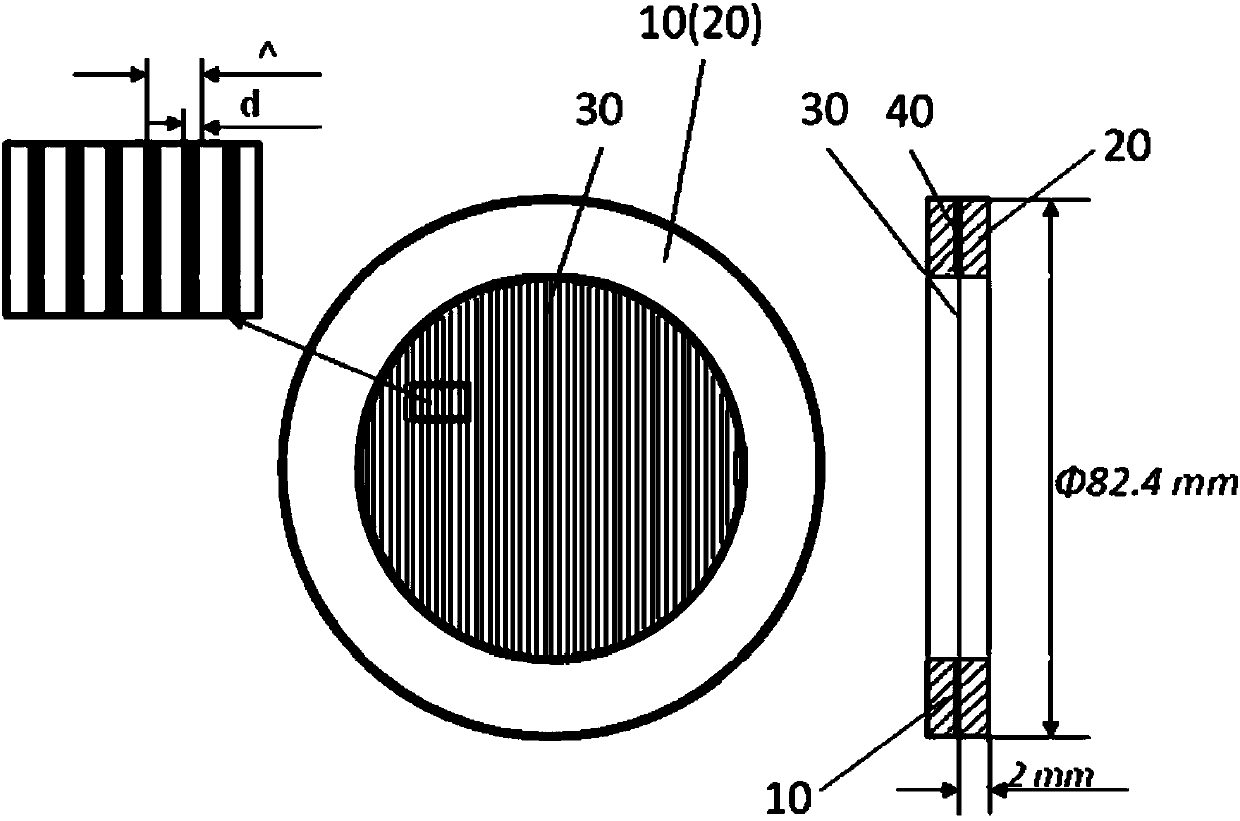
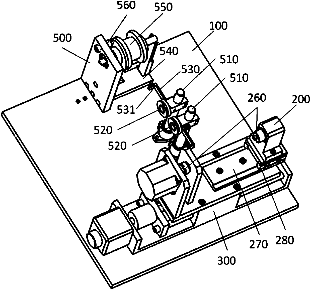

Image

  • Wire grid structure and manufacturing apparatus thereof
  • Wire grid structure and manufacturing apparatus thereof
  • Wire grid structure and manufacturing apparatus thereof

Examples


Embodiment Construction

[0025] Hereinafter, embodiments of the present invention will be described in detail with reference to the accompanying drawings. This invention may, however, be embodied in many different forms and should not be construed as limited to the specific embodiments set forth herein. Rather, the embodiments are provided to explain the principles of the invention and its practical application, thereby enabling others skilled in the art to understand the invention for various embodiments and with various modifications as are suited to particular intended uses.

[0026] In the drawings, the thicknesses of layers and regions are exaggerated for clarity. Like reference numerals refer to like elements throughout the drawings.

[0027] It will be understood that, although the terms "first", "second", etc. may be used herein to describe various elements, these elements should not be limited by these terms. These terms are only used to distinguish one element from another.

[0028] figu...


PUM


Abstract

The invention provides a wire grid structure of a terahertz wave band. The structure comprises a first circular ring, a second circular ring and a plurality of metal lines. The first circular ring and the second circular ring are bonded to each other, the plurality of metal wires are clamped and arranged at equal intervals between the first circular ring and the second circular ring, and each of the metal wires stretches across inner circles of the first circular ring and the second circular ring. The invention also provides a manufacturing apparatus of the wire grid structure. A method for manufacturing the metal grid structure in the invention is simple and a yield is high. Compared to a wire grid acquired by a traditional photolithography technology, by using the wire grid structure of the invention, cost can be greatly reduced on the basis of improving performance. In addition, since the wire grid structure of the invention is formed through separation after being winded by a winding method through using automatic control, substrate support does not need so as to eliminate an influence of interference and thus polarization transmission performance is increased.

Description

technical field [0001] The invention belongs to the technical field of wire grid manufacturing, and in particular relates to a wire grid structure in the terahertz band and a manufacturing device thereof. Background technique [0002] Terahertz waves are located at 0.3THz-30THz (wherein, 1THz=10 12 Hz, the wavelength is about 10μm-1mm, and the photon energy is about 1.2meV-120meV) The electromagnetic wave in the spectrum range, which is between the millimeter wave and the infrared wave, is the transition area from electronics to photonics, and is also a part of the electromagnetic spectrum. very important band. [0003] Compared with traditional light sources, terahertz radiation sources have unique and excellent characteristics such as coherence, low energy, and strong penetrating ability. Applied research fields such as imaging, environmental monitoring, food inspection, radio astronomy, satellite communication and weapon guidance all have great scientific research value...

Claims


Application Information

Patent Timeline
Patent Type & Authority Applications(China)
IPC IPC(8): G02B5/30
Inventor 秦华黄晶晶
Owner SUZHOU INST OF NANO TECH & NANO BIONICS CHINESE ACEDEMY OF SCI
Learn More