Ultralow boiler smoke emission device

A technology of emission device and boiler flue gas, applied in the field of flue gas purification, can solve the problem that denitrification, dust removal, and desulfurization technology cannot meet ultra-low emission standards, the flue gas particulate matter at the desulfurization outlet is increased, and desulfurization efficiency cannot meet ultra-low standards, etc. problems, to achieve the effect of reducing equipment operating costs, reducing pressure, and reducing NOX generation

Pending Publication Date: 2017-10-20
河南开祥精细化工有限公司
View PDF11 Cites 8 Cited by
  • Summary
  • Abstract
  • Description
  • Claims
  • Application Information

AI Technical Summary

Problems solved by technology

The limestone-gypsum method was developed earlier, but the investment and operating costs are relatively high, which is difficult for enterprises to bear
Ammonia desulfurization has the advantages of small footprint, low investment, no increase in carbon emissions, no waste water and waste residue, suitable for various coal types, high utilization value of by-product ammonium sulfate, and obvious economic benefits, but the desulfurization efficiency cannot reach Ultra-low standards, the formation of aerosols lead to the disadvantage of increasing flue gas particulate matter at the desulfurization outlet
[0006] In summary, the current denitrification, dust removal, and desulfurization technologies for flue gas alone cannot meet the ultra-low emission standards stipulated by the state, and it is imminent to design new boiler flue gas purification equipment

Method used


Image

  • Ultralow boiler smoke emission device
  • Ultralow boiler smoke emission device
  • Ultralow boiler smoke emission device

Examples


Embodiment Construction

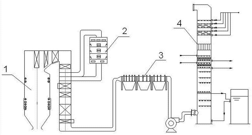
[0023] like figure 1 As shown, a boiler flue gas ultra-low emission device according to the present invention includes a coal-fired boiler 1, a denitration reactor 2, a bag filter 3 and a desulfurization tower 4, and the flue gas generated by the coal-fired boiler 1 passes through the denitration reaction in sequence 2, bag filter 3 and desulfurization tower 4 and then discharged.

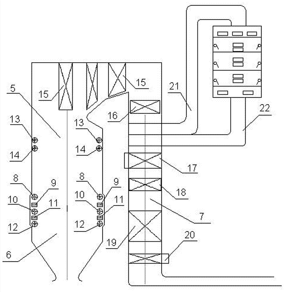
[0024] like figure 2 As shown, the coal-fired boiler 1 of the present invention includes a furnace 5, a main burner 6 and a flue 7, the main burner 6 is arranged at the bottom of the furnace 5, and the main burner 6 is sequentially provided with upper two Secondary air spout 8, last wind spout 9, middle secondary air spout 10, next air spout 11 and following secondary air spout 12, wherein the area of ​​the last secondary air spout 8 and the middle secondary air spout 10 are 1 / 2 of the area of ​​the lower secondary air spout 12. The dense phase side of the previous wind is at the bottom, the di...


PUM


Abstract

The invention discloses an ultralow boiler smoke emission device. The ultralow boiler smoke emission device comprises a coal fired boiler, a denitration reactor, a bag type dust remover and a desulfuration tower. The coal fired boiler comprises a hearth, a main combustor and a flue. The main combustor is arranged at the lower portion of the hearth. Two layers of over fire air spraying ports are formed in the upper portion of the hearth. A smoke guide-out pipeline and a smoke guide-in pipeline are arranged between a previous-level economizer and a previous-level air pre-heater in the flue and are connected with an inlet and an outlet of the denitration reactor correspondingly, and an outlet of the flue is sequentially connected with the bag type dust remover and the desulfuration tower. The desulfuration tower is internally provided with a washing section, an absorption section and a mist removing section from bottom to top. Two water washing spraying layers are arranged above the absorption section, and a PP filler layer is arranged between the upper water washing spraying layer and the lower water washing spraying layer. The mist removing section is sequentially provided with a pipe type mist remover and a ridge mist remover from bottom to top. By means of the ultralow boiler smoke emission device, the content of NOX, SO2 and soot in the boiler smoke can be reduced, the national ultralow emission standard is met, and long-period running target of the device is achieved.

Description

technical field [0001] The invention relates to the technical field of flue gas purification, in particular to a boiler flue gas ultra-low emission device. Background technique [0002] Most of the smog comes from industrial carbon emissions, among which the flue gas emissions from boilers are the main cause of air pollution. As people's living standards are getting higher and higher, the country's environmental governance is becoming increasingly stringent, requiring coal-fired units to meet ultra-low emission standards (NO X <50mg / m³, SO 2 <35mg / m³, dust content <10mg / m³). [0003] At present, the smoke and dust in the flue gas are mainly removed by dust collectors. More advanced dust removal methods include electric dust removal, bag dust removal and electric bag dust removal. The power consumption of electrostatic precipitator is large, the electrode is easy to be grounded, the failure rate is high, it cannot be operated for a long period, and the dust remova...

Claims


Application Information

Patent Timeline
Patent Type & Authority Applications(China)
IPC IPC(8): F22B31/00F22B31/08F23C5/08F23C7/00F23J15/00F23J15/04F23J15/02B01D53/78B01D53/75B01D53/50B01D50/00B01D46/02B01D53/90B01D53/56
CPCB01D46/023B01D50/00B01D53/502B01D53/75B01D53/78B01D53/8628B01D53/90F22B31/00F22B31/08F23C5/08F23C7/00F23J15/006F23J15/02F23J15/025F23J15/04F23J2215/10F23J2215/20F23J2217/10F23J2219/40F23J2219/10B01D2258/0283Y02E20/34
Inventor 张小勤李栓民刘兵伟李克新张方尚凤玲徐相锋赵强强刘洋姬红闯
Owner 河南开祥精细化工有限公司
Why Eureka
Try Eureka