Novel rotary spraying stirrer for preventing oil sludge deposition of crude oil storage tank

A crude oil storage tank and rotary jet technology is applied in the field of devices used for preventing sludge deposition in crude oil storage tanks, which can solve the problems of accelerated rotation speed, large fluid energy loss, low transmission efficiency, etc., and achieves stable speed control, easy processing and manufacturing, The effect of small energy loss

Inactive Publication Date: 2017-10-13
BEIJING INSTITUTE OF PETROCHEMICAL TECHNOLOGY
View PDF18 Cites 5 Cited by
  • Summary
  • Abstract
  • Description
  • Claims
  • Application Information

AI Technical Summary

Problems solved by technology

No matter in terms of variety type or technical indicators, foreign rotary jet agitators are relatively mature, but objectively speaking, there are still the following disadvantages: (1) Due to the axial flow turbine at the entrance driven by fluid, the rotary jet agitator The energy loss of the fluid is large due to the rotation of the agitator, which in turn affects the jet impact force on the sludge to a certain extent; (2) The rotation speed of the rotary jet agitator is controlled by a three-stage worm gear transmission, and the transmission efficiency of this deceleration mode is low , the design and processing are more difficult; in addition, the entire rotary jet agitator rotates more parts, and the probability of damage and replacement is higher
In 2013, Jiang Weimin of Fushun, Liaoning applied for a utility model patent - speed-controlled rotary jet agitator (ZL 201320416513.1), which has six nozzles, but did not mention the specific type of gear mechanism
Although the above rotary jet agitators with gear mechanism have been greatly improved and improved compared with the rotary jet agitator without gear mechanism, there are still many deficiencies, the biggest disadvantage of which is: The reduction ratio of the gear mechanism for speed control is too small, only tens or hundreds
When the jet flow of the rotary jet agitator is large, the fluid drives the axial-flow hydraulic turbine to rotate faster, and the rotation speed of the rotary jet agitator shell is accelerated due to the small deceleration ratio, and it is difficult to have enough impact time on the sludge in a certain direction , the ability to prevent sludge deposition is weak
On the other hand, due to the small effective radius of the injection, the stirring and mixing efficiency of the crude oil in the entire tank is low and the effect is poor.

Method used


Image

  • Novel rotary spraying stirrer for preventing oil sludge deposition of crude oil storage tank
  • Novel rotary spraying stirrer for preventing oil sludge deposition of crude oil storage tank
  • Novel rotary spraying stirrer for preventing oil sludge deposition of crude oil storage tank

Examples


specific Embodiment approach

[0019] The novel rotary jet agitator used for preventing oil sludge deposition in crude oil storage tank of the present invention, its preferred specific embodiment is:

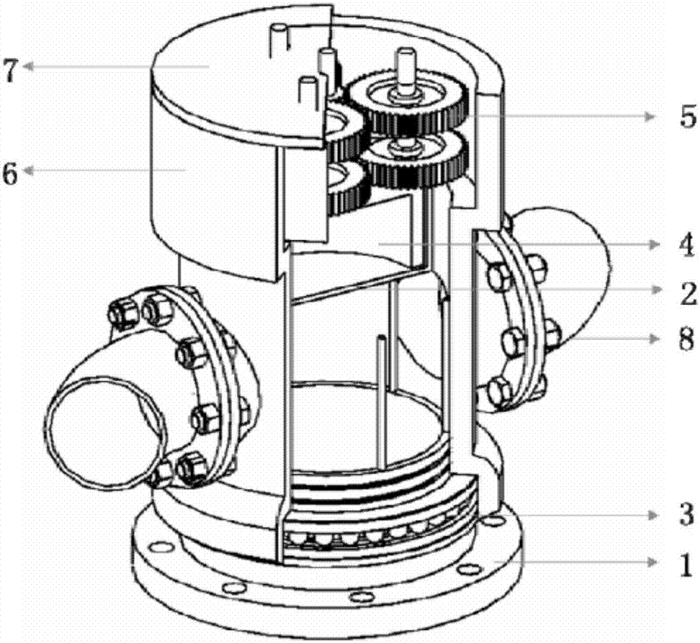
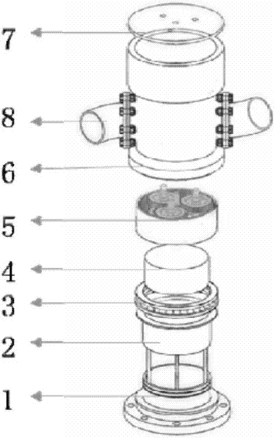
[0020] Including the fixed base, the outer cylinder of the hydraulic damper, the thrust bearing, the inner cylinder of the hydraulic damper, the planetary gear mechanism, the rotating shell, the top cover, and the nozzle;

[0021] The outer cylinder of the hydraulic damper and the inner cylinder of the hydraulic damper together form a hydraulic damper, the lower end of the hydraulic damper is connected to the fixed base, and the input shaft at the upper end is connected to the output shaft of the planetary gear mechanism;

[0022] The fixed base is connected with the outer cylinder of the hydraulic damper through supporting ribs;

[0023] The nozzle is connected to the rotating shell through a flange, and the nozzle is an arc-shaped curved nozzle arranged concentrically or a straight nozzle arranged eccentric...

specific Embodiment

[0032] Such as Figure 1a to Figure 5b As shown, the rotary jet agitator and the storage tank, oil pipeline, valves and oil pumps form a rotary jet agitator system.

[0033] The oil pump pumps the crude oil from the bottom of the storage tank and transports it through the oil pipeline to the bottom inlet of the rotary ejector installed on the inner wall of the storage tank or at the center of the storage tank. The rotary jet agitator and the oil pipeline are connected by an 8-inch standard flange. If necessary, a reinforcing rib is set between the oil pipeline and the ground at the connection between the two to prevent the rotary jet agitator from shaking when it is working. The structure of the rotary jet agitator mainly includes a fixed base 1, a hydraulic damper outer cylinder 2, a thrust bearing 3, a hydraulic damper inner cylinder 4, a planetary gear mechanism 5, a rotating housing 6, a top cover 7, and a nozzle 8; The fixed base 1, the bottom of the hydraulic damper out...


PUM


Abstract

The invention discloses a novel rotary spraying stirrer for preventing oil sludge deposition of a crude oil storage tank. The novel rotary spraying stirrer comprises a fixed pedestal, a hydraulic damper outer cylinder, a thrust bearing, a hydraulic damper inner cylinder, a planet gear mechanism, a rotary shell, a top cover and a nozzle; the hydraulic damper outer cylinder and the hydraulic damper inner cylinder jointly form a hydraulic damper; the lower end of the hydraulic damper is connected with the fixed pedestal; an output shaft at the upper end of the hydraulic damper is connected with an output shaft of the planet gear mechanism; the fixed pedestal is connected with the hydraulic damper outer cylinder via a supporting fin. When fluid passes through a rotary spraying stirrer flow channel and is sprayed out of the nozzle, the ejected flow generates a contrary action force on the shell of the rotary spraying stirrer, so that the shell of the rotary spraying stirrer is driven to rotate. The novel rotary spraying stirrer is small in energy loss, stable in speed control, easy to process and produce and low in price, and can be applied to prevention of oil sludge deposition of the crude oil storage tank, occasions of blending and homogenizing crude oil, component oil, lubricating oil and the like in oil product tanks and occasions of cleaning and dredging storage tanks.

Description

technical field [0001] The invention relates to a device for preventing oil sludge deposition in crude oil storage tanks, in particular to a novel rotary jet agitator for preventing oil sludge deposition in crude oil storage tanks. Background technique [0002] With the continuous development of the world economy, oil consumption has increased sharply. At the same time, with the advancement of the construction of strategic oil reserves in various countries, the number and capacity of crude oil storage tanks will increase day by day. During the storage of crude oil, oil phase stratification will occur due to the difference in density, resulting in different properties such as acid value and viscosity of crude oil in each layer in the storage tank, which is not conducive to the proportioning of crude oil and affects the stable operation of downstream refining units On the other hand, asphaltene, colloid, wax, etc. in crude oil are easy to aggregate and deposit to the bottom of...

Claims


Application Information

Patent Timeline
Patent Type & Authority Applications(China)
IPC IPC(8): B01F5/02B01F15/00B65D88/68
CPCB65D88/68B01F25/2122B01F35/32015
Inventor 陈家庆王强强姬宜朋丁国栋蔡小垒
Owner BEIJING INSTITUTE OF PETROCHEMICAL TECHNOLOGY
Why Eureka
Try Eureka