A Distributed Attenuation Confocal Waveguide Cyclotraveling Wave Tube High Frequency System

A technology of traveling wave tube and waveguide, which is applied in the field of confocal waveguide gyrotraveling wave tube, can solve the problems such as the output signal has not been obtained, and achieve the effect of reducing diffraction loss, reducing diffraction loss, and large diffraction loss

Active Publication Date: 2019-03-05
UNIV OF ELECTRONICS SCI & TECH OF CHINA
View PDF2 Cites 0 Cited by
  • Summary
  • Abstract
  • Description
  • Claims
  • Application Information

AI Technical Summary

Problems solved by technology

The China Academy of Engineering Physics has only obtained the result of zero drive stability in the test, and has not yet obtained a stable output signal

Method used


Image

  • A Distributed Attenuation Confocal Waveguide Cyclotraveling Wave Tube High Frequency System
  • A Distributed Attenuation Confocal Waveguide Cyclotraveling Wave Tube High Frequency System
  • A Distributed Attenuation Confocal Waveguide Cyclotraveling Wave Tube High Frequency System

Examples


Embodiment Construction

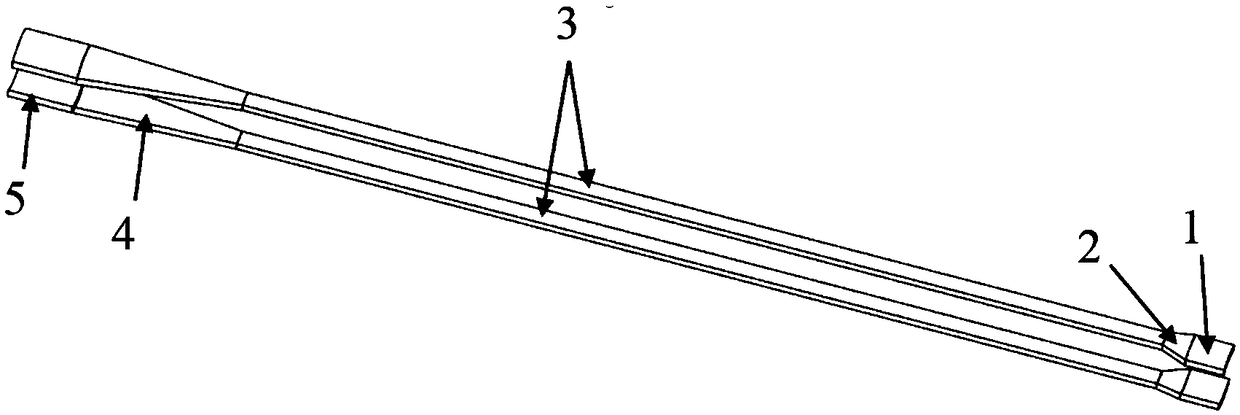
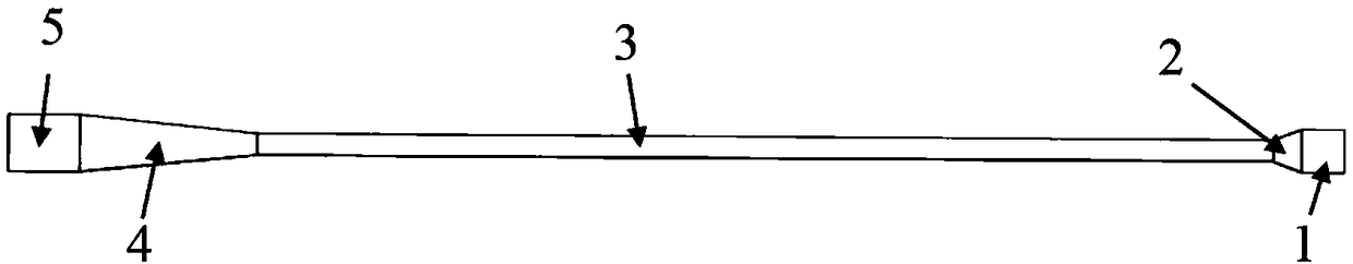
[0018] In the following, the present invention will be further described in detail through the design example of the high-frequency system of the W-band distributed attenuation confocal waveguide gyrotraveling wave tube and the accompanying drawings.

[0019] The reason why the confocal waveguide has mode-selective properties is that its laterally open structure causes it to generate diffraction losses, which are different for different modes. Modes working in confocal waveguides are generally HE mn Mode, for the mode of m = 0, the energy is concentrated in the center of the mirror, so there is only weak edge attenuation. For modes with m>0, most of the energy is closer to the edge of the mirror and thus is more easily lost. In the confocal waveguide gyrotraveling wave tube, we generally only care about HE 0n model. In this embodiment, the distance between the two mirrors of the confocal waveguide is known to be 7mm, so the working mode HE mn is ok for HE 04 mold. Table ...


PUM


Abstract

The invention discloses a distributed attenuation confocal waveguide cyclotron traveling wave tube high-frequency system, which belongs to the technical field of microwave, millimeter wave and terahertz devices. The structure consists of a confocal waveguide with upper and lower symmetry and open sides. The confocal waveguide has a consistent mirror curvature, including an input uniform section, an input gradient section, an interaction section, an output gradient section, and an output uniform part. The structure uses a confocal waveguide interaction section with a narrow mirror width to cut off the return wave oscillation loop of the spurious mode, while ensuring that the interaction section is long enough to achieve a high linear gain. Furthermore, the diffraction loss of the amplified high-frequency field is reduced by increasing the mirror width of the output uniform segment, thereby improving the output power and overall efficiency of the working mode.

Description

technical field [0001] The invention belongs to the technical field of microwave, millimeter wave and terahertz devices, in particular to a high-frequency system of a distributed attenuation confocal waveguide gyrotraveling wave tube, which can be applied to the confocal waveguide gyrotraveling wave tube in millimeter wave and terahertz bands. Background technique [0002] With the rapid development of modern high-performance radar and long-distance communication technology, the requirements of the system for the operating frequency, power, bandwidth and other performance of the signal source are increasing day by day. The interaction structure of the gyrotron TWT is a smooth waveguide, which can theoretically achieve higher efficiency and wider bandwidth than other gyrotron devices. However, it is precisely because of the smooth waveguide interaction structure of the gyro TWT that it is prone to various parasitic oscillations, which will seriously affect the performance of ...

Claims


Application Information

Patent Timeline
Patent Type & Authority Patents(China)
IPC IPC(8): H01J23/36
CPCH01J23/36
Inventor 王建勋姚叶雷田启知罗勇
Owner UNIV OF ELECTRONICS SCI & TECH OF CHINA
Why Eureka
Try Eureka